

Portable radiant heater with two reflectors
a radiant heater and portable technology, applied in the field of portable radiant heaters, can solve the problems of inconvenient installation, increased bulkiness of such space heaters, and disadvantage in many applications
- Summary
- Abstract
- Description
- Claims
- Application Information
AI Technical Summary
Benefits of technology
Problems solved by technology
Method used
Image

Examples
Embodiment Construction
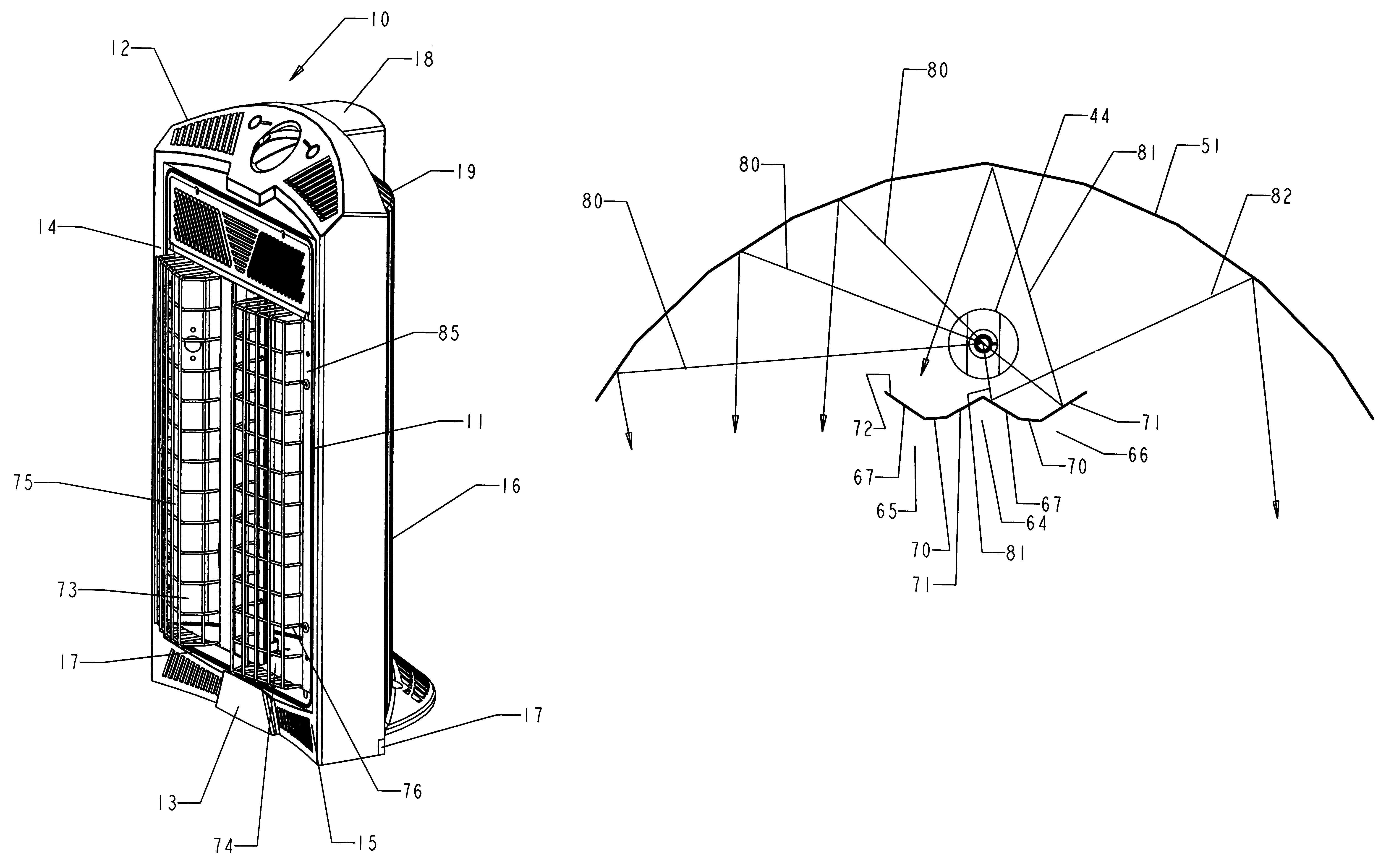
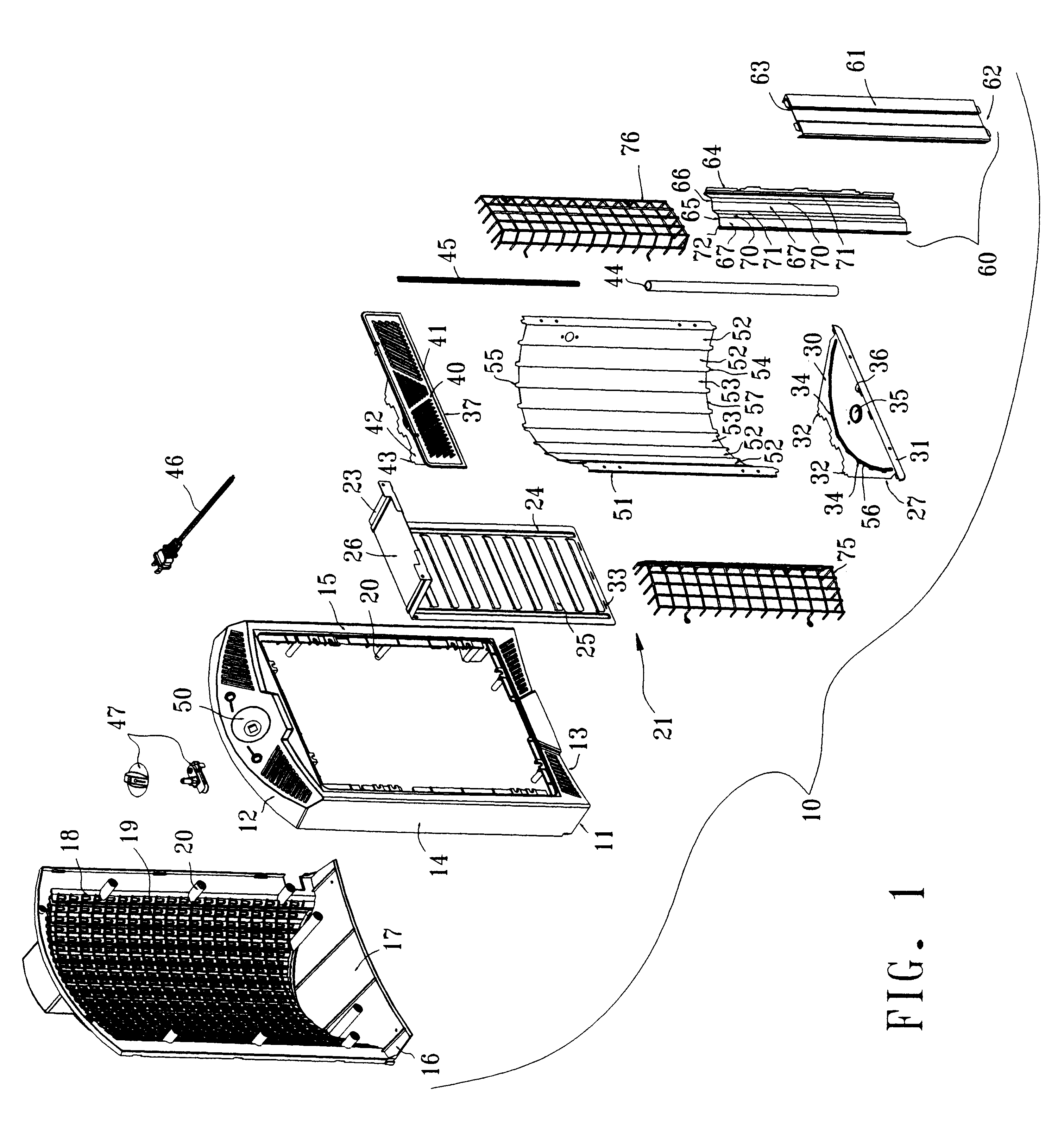
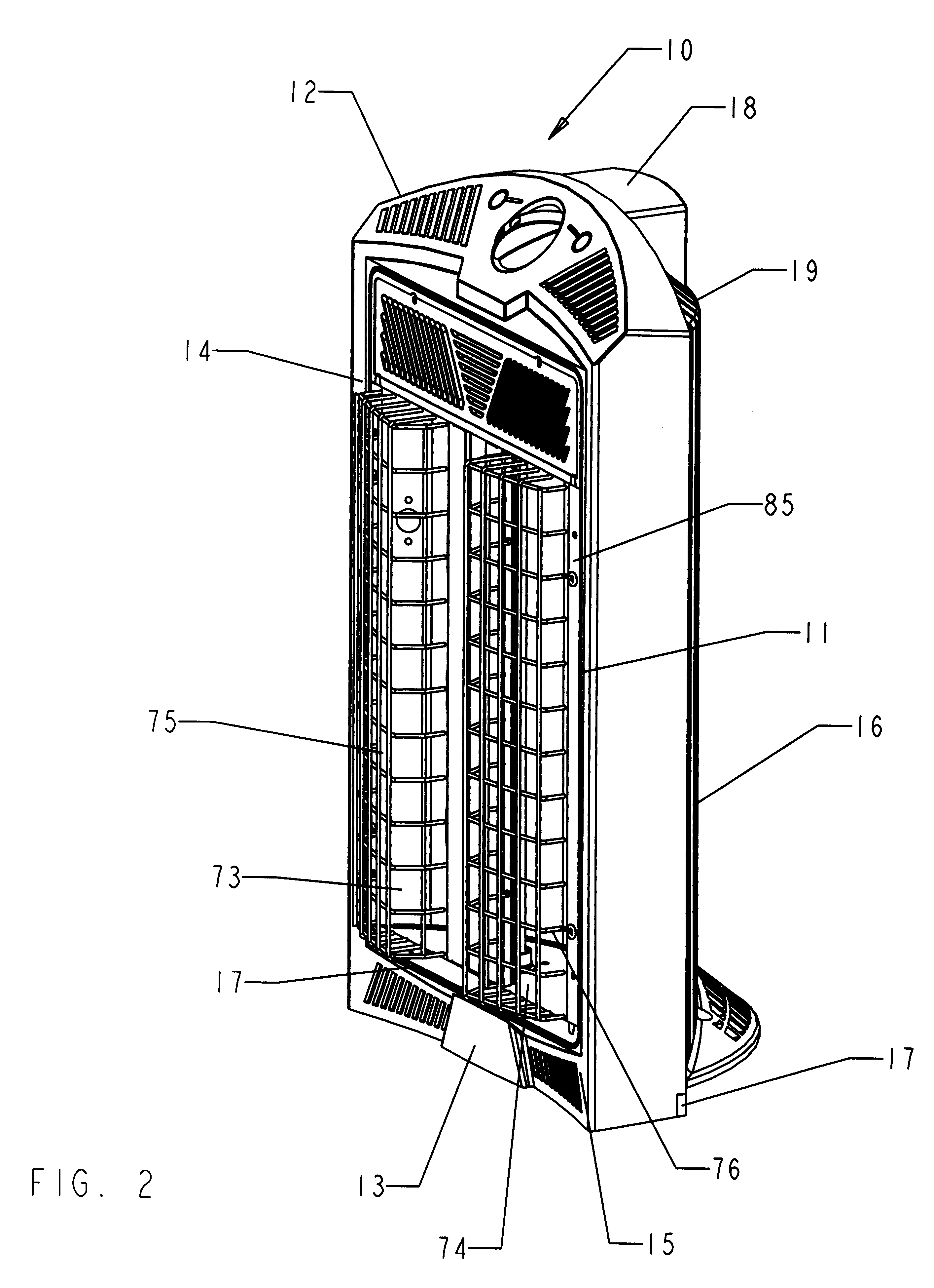
Now referring to FIGS. 1 and 2, a portable radiant heater 10 constructed in accordance with this invention includes an open housing frame 11 designed to be in a vertical orientation having a top cross member 12, a bottom cross member 13 and left and right side walls 14 and 15 respectively in the orientation of FIG. 1. A rear housing 16 includes a base 17 and a vertical back wall 18 that curves about a vertical axis. The curved vertical back wall 18 may include an array 19 of air passages. Any number of specific arrays could be substituted for the specifically disclosed array provided that the sizes of individual air passages met various standards required for such devices. The housing frame 11 and rear housing portion 16 are formed into an integral structure through by plastic connectors 20 or other fasteners.
The housing frame 11 carries a subassembly 21 that includes a bracket 23 that has a back portion 24 with an optional array 25 of air passages and a top plate 26 at right angles...
PUM
| Property | Measurement | Unit |
|---|---|---|
| circumference | aaaaa | aaaaa |
| width | aaaaa | aaaaa |
| energy | aaaaa | aaaaa |
Abstract
Description
Claims
Application Information