Machine and method for rehabilitating a ballast bed

a ballast bed and machine body technology, applied in the direction of roads, measuring devices, constructions, etc., can solve the problems of inability to prevent inaccuracy caused by twisting or deflection of the fram

Inactive Publication Date: 2001-02-20
FRANZ PLASSER BAHNBAUMASCHINEN IND GMBH
View PDF8 Cites 9 Cited by
  • Summary
  • Abstract
  • Description
  • Claims
  • Application Information

AI Technical Summary

Problems solved by technology

Since reproducing the position of the track is accomplished via the second frame...

Method used


Image

  • Machine and method for rehabilitating a ballast bed
  • Machine and method for rehabilitating a ballast bed
  • Machine and method for rehabilitating a ballast bed

Examples


Embodiment Construction

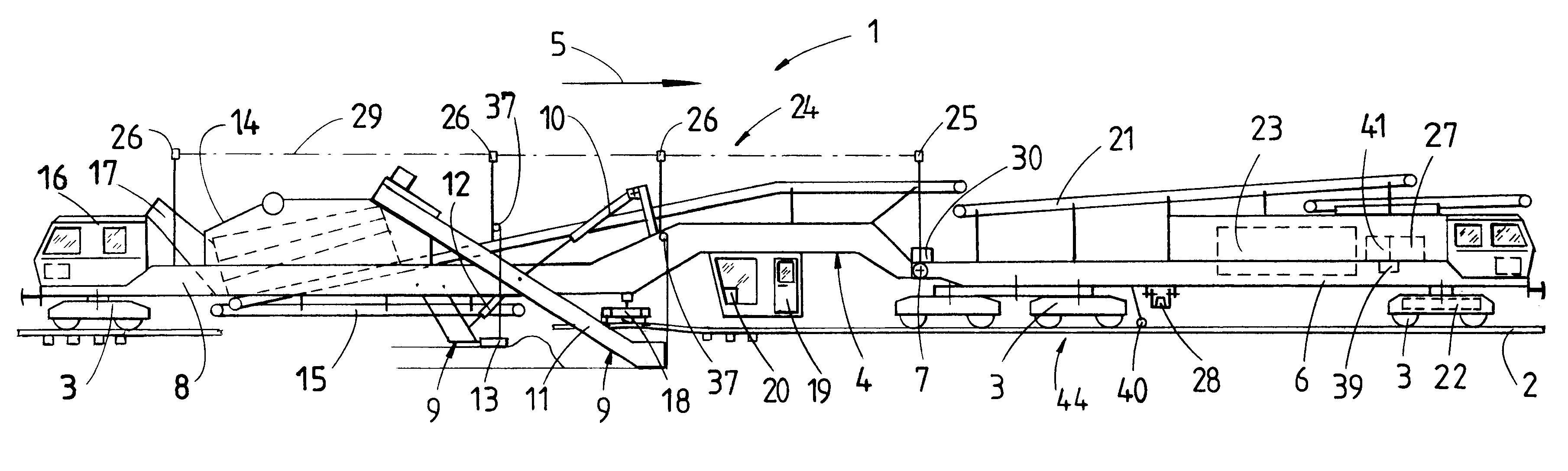
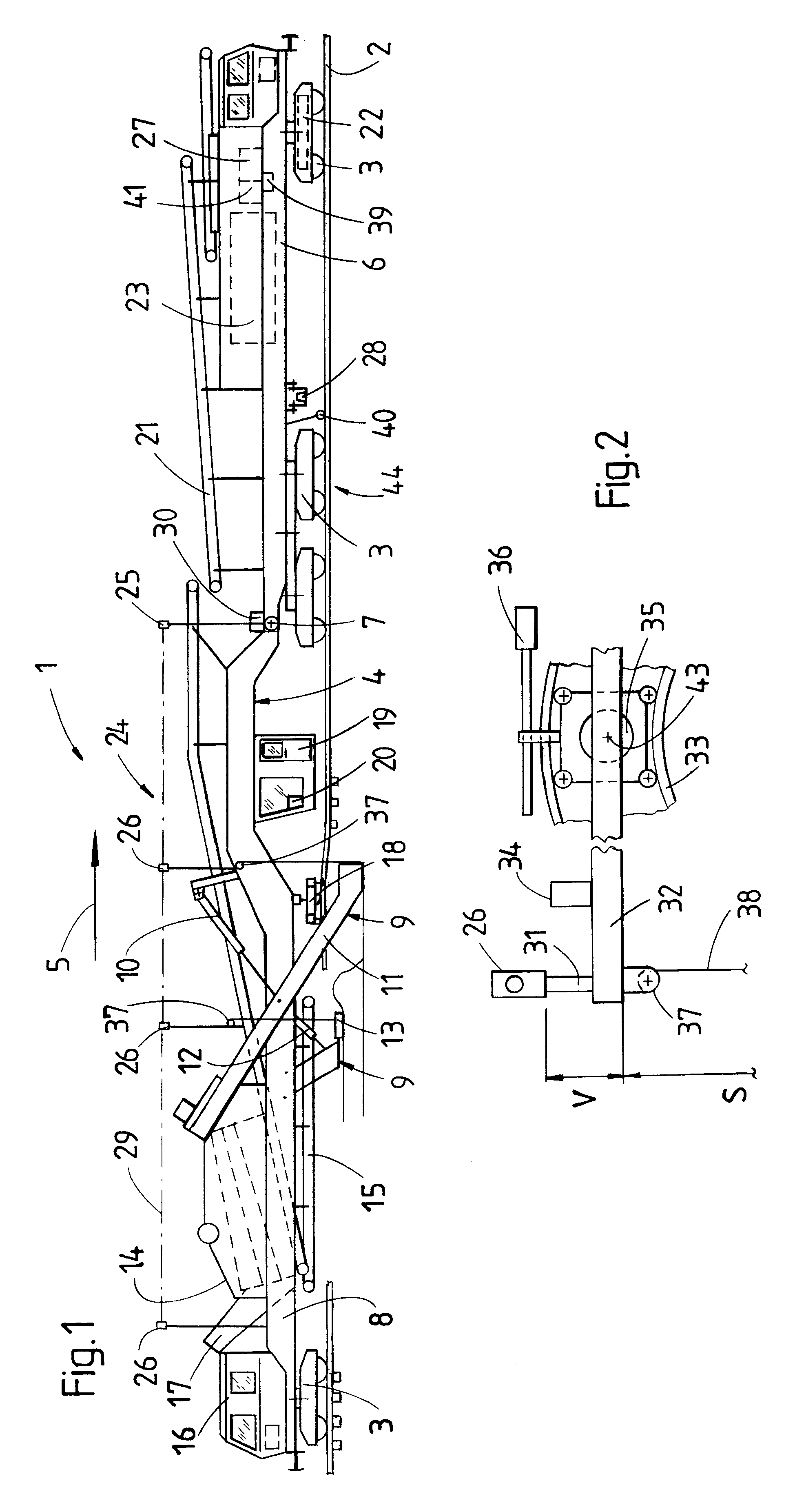
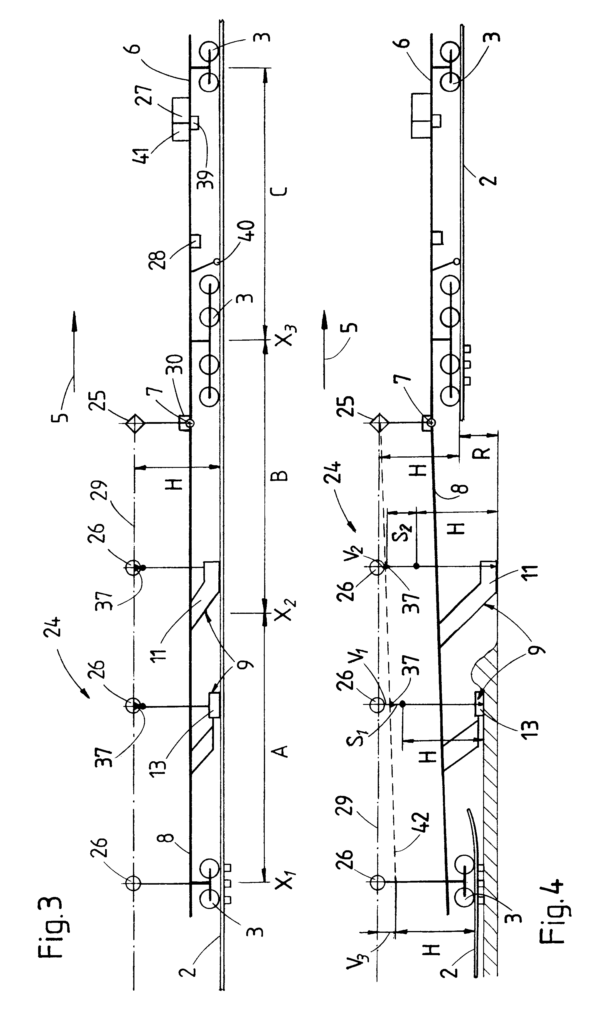
Referring now to the drawing and first to FIG. 1, there is shown a track working machine 1 for cleaning ballast of a ballast bed 44 supporting a track 2 extending in a longitudinal direction. The machine has a machine frame 4 which extends in the longitudinal direction and is supported on the track 2 by undercarriages 3 for mobility in an operating direction indicated by arrow 5. The machine frame 4 is composed of a first frame part 6, located in front with respect to the operating direction, and a rearward, second frame part 8 connected thereto via an articulation 7.

Located on the second frame part 8 are working units 9 constructed for treating the ballast bed 44, the working units having the shape of a clearing chain 11, vertically adjustable by a drive 10, as well as a grading chain 13 which is vertically adjustable by a drive 12 and immediately follows said clearing chain 11. A vibratable screening arrangement 14 is provided for cleaning the ballast taken up by the clearing chai...


PUM


Abstract

A machine frame of a ballast bed rehabilitation machine is composed of two articulatedly coupled frame parts. A longitudinal inclination meter is mounted on the leading frame part, in the working direction, for detecting the inclination of the track. A laser reference system is provided for controlling the position of vertically adjustable track working units arranged on the trailing frame part, the laser reference system being formed by a laser transmitter, equipped for relative adjustment of a reference plane by means of an adjusting device, and laser receivers. A control device is designed for the time-delayed delivery, in dependence upon the distance travelled, of a longitudinal inclination value detected by the longitudinal inclination meter to the adjusting device of the laser transmitter. The reference plane, used to guide the working units, is adjusted in accordance with the detected longitudinal track inclination.

Description

1. Field of the InventionThe present invention relates to a mobile track working machine for rehabilitating a ballast bed supporting a track extending in a longitudinal direction, comprising a machine frame extending in the longitudinal direction and supported on the track by undercarriages for mobility in an operating direction. The machine frame is composed of a first frame part, leading in the operating direction, and a second frame part linked thereto. A longitudinal inclination meter is mounted on the first frame part for detecting an inclination of the track in the longitudinal direction. Working units are mounted on the second frame part, the working units being adjustable with respect to a vertical direction. A laser reference system is arranged on the machine frame for controlling the vertical position of the working units, the laser reference system being formed by a laser transmitter for establishing a reference plane and laser receivers for detecting said reference plane...

Claims


Application Information

Patent Timeline
IPC IPC(8): E01B35/00E01B27/10E01B35/08E01B35/06
CPCE01B35/00
Inventor THEURER, JOSEFLICHTBERGER, BERNHARD
Owner FRANZ PLASSER BAHNBAUMASCHINEN IND GMBH
Why Eureka
Try Eureka