This helps you quickly interpret patents by identifying the three key elements:
Problems solved by technology
Method used
Benefits of technology
Problems solved by technology
However, only limited axial installation space is available when the transmission is installed frontally and transversely in the vehicle
Method used
Image
Click on the blue label to locate the original text in one second.
Reading with bidirectional positioning of images and text.
Examples
Embodiment Construction
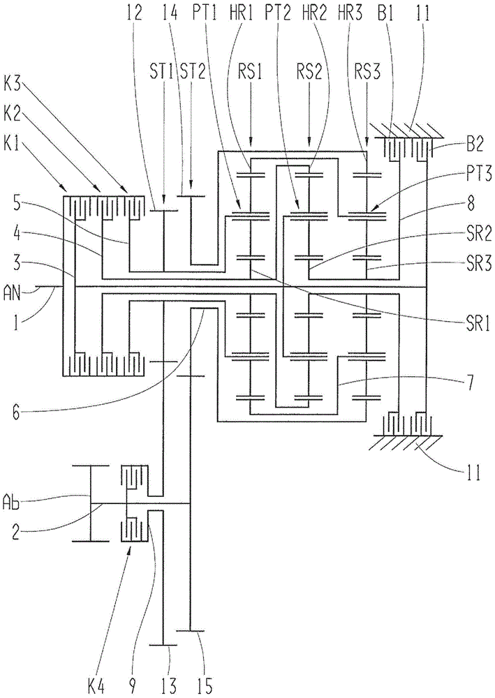
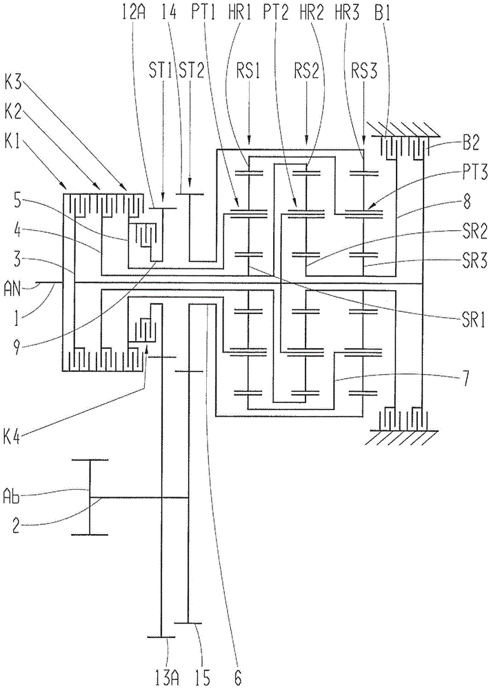
[0020] exist figure 1 with figure 2 In each case, an embodiment variant of the multi-stage transmission in the form of a planetary structure according to the invention for a vehicle, eg as an automated transmission or an automatic transmission, is shown by way of example.
[0021] Independently of the respective embodiment variant, the multi-stage transmission comprises a housing 11 indicated only schematically, which has a first shaft 1 as drive element An and an output element arranged axially parallel thereto. The second axis 2 of Ab and the other seven axes 3, 4, 5, 6, 7, 8, 9. Furthermore, a first planetary gearset RS1 , a second planetary gearset RS2 and a third planetary gearset RS3 are provided, which are preferably designed as negative planetary gearsets. For shifting several gear stages, a first shifting element K1 embodied as a clutch, a second shifting element K2 embodied as a clutch, a third shifting element K3 embodied as a clutch, a fourth shifting element em...
PUM
Abstract
The invention relates to a multi-stage planetary transmission for a vehicle, comprising a housing (11), a first shaft (1) being provided as the drive (An) and a second shaft (2), arranged axially parallel thereto, as the output (Ab). Three planetary gear sets (RS1, RS2, RS3) and additional shafts (3, 4, 5, 6, 7, 8, 9) as well as six shift elements (K1, K2, K3, K4, B1, B2) are provided the actuation of which allows for a plurality of speeds, and machine elements (ST1, ST2) are provided for torque transmission between the drive (An) and the output (Ab). The first shaft (1) as the drive (An) can be connected to the planet carrier (PT2) of the second planetary gear set (RS2), to the sun gear (SR1) of the first planetary gear set (RS1), to the ring gear (HR2) of the second planetary gear set (RS2), to the planet carrier (PT1) of the first planetary gear set (RS1) and to the first machine element (ST1), and the second shaft (2) as the output (Ab) is or can be connected to the first machine element (ST1) and to the second machine element (ST2).
Description
technical field [0001] The invention relates to a multi-stage transmission in a planetary configuration for a vehicle according to the type defined in the preamble of claim 1 . Background technique [0002] For example, a power shiftable multi-stage transmission is known from DE 10 2007 014 150 A1. In this multi-stage transmission, the drive shaft is firmly connected to the first shaft of the first shaft train via a torsional vibration damper. Furthermore, a second shaft system arranged parallel thereto contains a driven shaft called the second shaft. The two shaft systems are connected to each other via three spur gear stages. A three-shaft first planetary gear stage is located on the first shaft train. A second planetary gear stage and a third planetary gear stage are located on the second shaft train. The multi-stage transmission thus comprises ten shafts, which are connected to one another via three spur gear stages and three planetary gear stages. In order to shift...
Claims
Application Information
Patent Timeline
Application Date:The date an application was filed.
Publication Date:The date a patent or application was officially published.
First Publication Date:The earliest publication date of a patent with the same application number.
Issue Date:Publication date of the patent grant document.
PCT Entry Date:The Entry date of PCT National Phase.
Estimated Expiry Date:The statutory expiry date of a patent right according to the Patent Law, and it is the longest term of protection that the patent right can achieve without the termination of the patent right due to other reasons(Term extension factor has been taken into account ).
Invalid Date:Actual expiry date is based on effective date or publication date of legal transaction data of invalid patent.

