Reversible fulcrum for a strut

a fulcrum and strut technology, applied in the direction of rail brake actuation, railway braking system, railway components, etc., can solve the problems of high torsional moments between the strut and the lever itself, high wear of the lever-strut assembly components, and the need for frequent maintenan

Inactive Publication Date: 2001-02-27
STUCKI DE MEXICO S DE R L DE C V
View PDF8 Cites 14 Cited by
  • Summary
  • Abstract
  • Description
  • Claims
  • Application Information

AI Technical Summary

Problems solved by technology

Because of the rigidity of this welded structure, several problems come up during normal use.
The lever-strut assembly is supposed to work at a 400 angle rigidly, however due to small gaps between components and undesirable forces produced by the railway car movements during running this angle normally varies few degrees, induc...

Method used


Image

  • Reversible fulcrum for a strut
  • Reversible fulcrum for a strut
  • Reversible fulcrum for a strut

Examples


Embodiment Construction

.

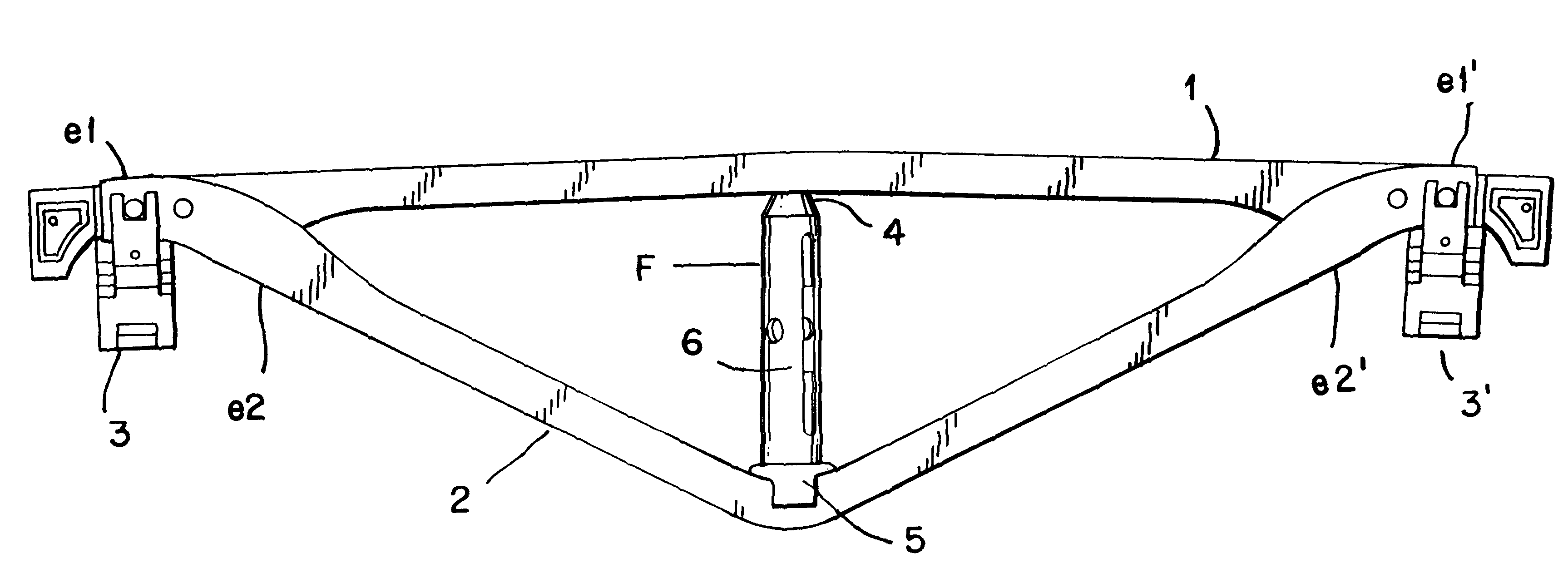
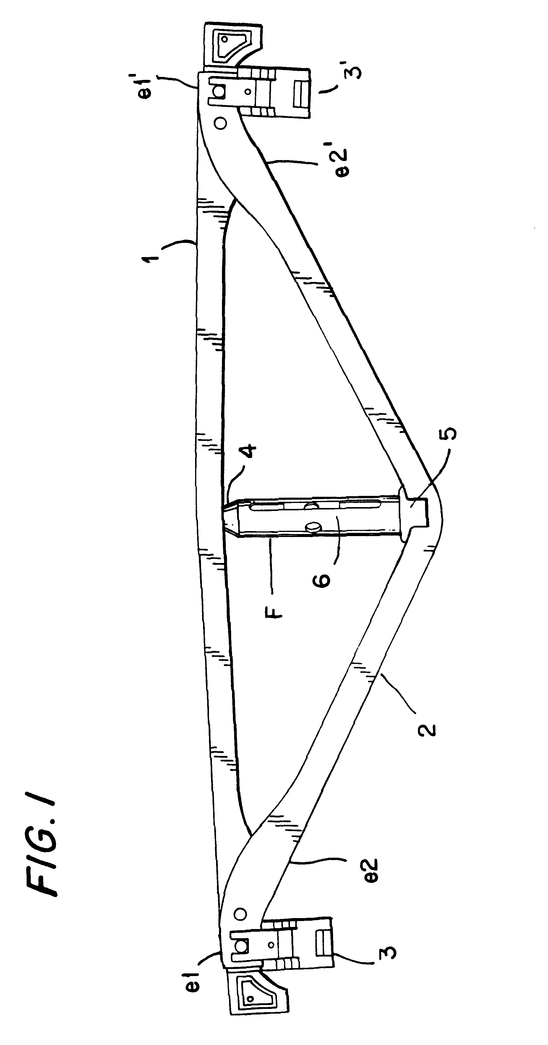
The reversible fulcrum, of the present invention, by which the strut can be converted from a right strut to a left strut and vice versa, will be now firstly described in relation to a brake beam, in accordance with its most general embodiment thereof, comprising:

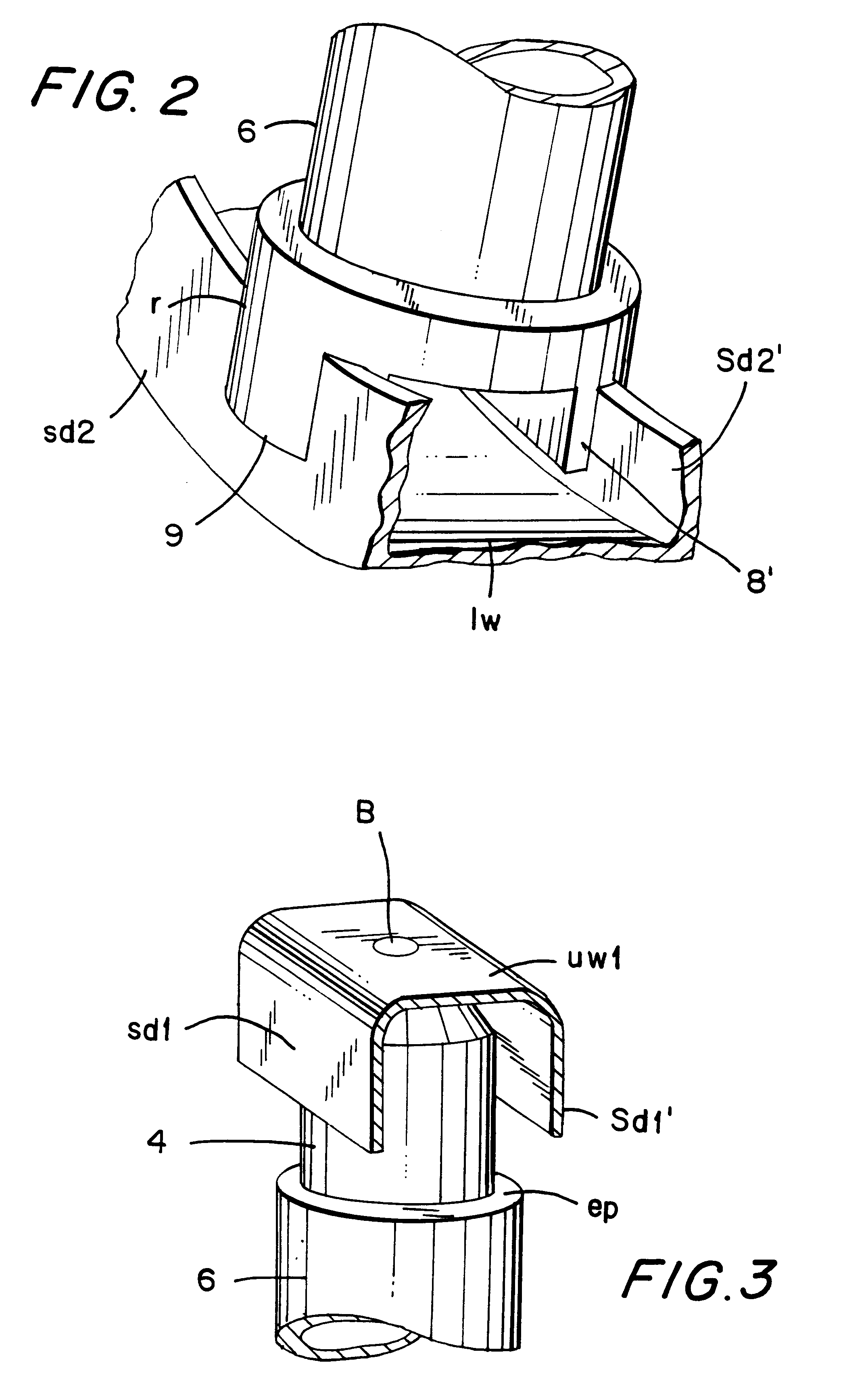
a compression member 1, having a first end e1 and a second end e1', said compression member 1 having a channel shaped cross section including an upper wall uw1 and two depending side walls sd1, sd1', each depending from an edge of the upper wall uw1 and a bore B in a central longitudinal portion of the upper wall uw1;

a "V" shaped tension member 2 having a first end e2 and a second end e2' each of which is respectively joined to an end e1, e1' of the compression member 1, said "V" shaped tension member having a channel shaped cross section including a lower wall lw and two upwardly projecting side walls sd2,sd2', each depending from an edge of the lower wall lw;

two brake shoes 3, 3', each respectively linked to each end of t...


PUM


Abstract

A strut having a reversible fulcrum, which can be changed, from a left strut to a right strut, for using in brake beams of the type comprising; a compression member, a "V" shaped tension member having a central apex coupled to the ends of the compression member; a brake shoe linked to the each end of the compression member; and a strut, wherein the strut having a reversible fulcrum comprising: a fulcrum body having a first end and a second end, a central slot passing through a central portion of the fulcrum body at a side portion thereof and an off-center pinhole passing through the fulcrum body at a central portion of a front portion of the fulcrum body; a hollow bell joint, having a dome rotary coupled to a central portion of the tension member and a tubular open end at which the first end of the fulcrum body is coupled; and a crown joint having a first end including an internal annular border, rotary receiving the second end of the fulcrum body, and a second end having two opposite holding skirts to be coupled to the central apex of the tension member.

Description

A. Field of the InventionThis invention relates to brake beams, and more particularly to a strut having a reversible fulcrum for using in brake beams of railway cars, which can be changed, from a left strut to a right strut.B. Description of the Related ArtThere are well known brake shoe assemblies for railway cars by which a brake shoe is pressed against a wheel in order to decrease or stop the rotational speed of the wheel and railway car.Generally, the brake shoe assembly is held by a structure called brake beam mounted transversely in the bogie of a railway car.The brake beam generally comprises a compression member, a generally "V" shaped tension member having its ends coupled to the ends of the compression member, a brake shoe linked to the each end of the compression member, and a strut welded to the compression member and tension member, so that the strut remains between the tension and compression members. Said strut is linked to a lever, which applies a force in order to p...

Claims


Application Information

Patent Timeline
IPC IPC(8): B61H13/36B61H13/00
CPCB61H13/36
Inventor ELIZALDE-SILLER, HUGO-RAMONMONTES-RAMOS, MIGUEL-ANGELHERNANDEZ-VARGAS, HUMBERTO
Owner STUCKI DE MEXICO S DE R L DE C V
Why Eureka
Try Eureka