Infrared seeker head for target seeking missile

a technology of infrared seeker and target, which is applied in the direction of direction controllers, instruments, weapons, etc., can solve the problems of missile guidance being totally interrupted, and modern picture processing infrared seeker heads are no longer as easily deceived

Inactive Publication Date: 2001-03-06
BODENSEEWERK GERATETECHNIK GMBH
View PDF12 Cites 32 Cited by
  • Summary
  • Abstract
  • Description
  • Claims
  • Application Information

AI Technical Summary

Problems solved by technology

Modern picture processing infrared seeker heads are no longer as easily deceived.
Then by dazzling and even destruction of th...

Method used


Image

  • Infrared seeker head for target seeking missile
  • Infrared seeker head for target seeking missile
  • Infrared seeker head for target seeking missile

Examples


Embodiment Construction

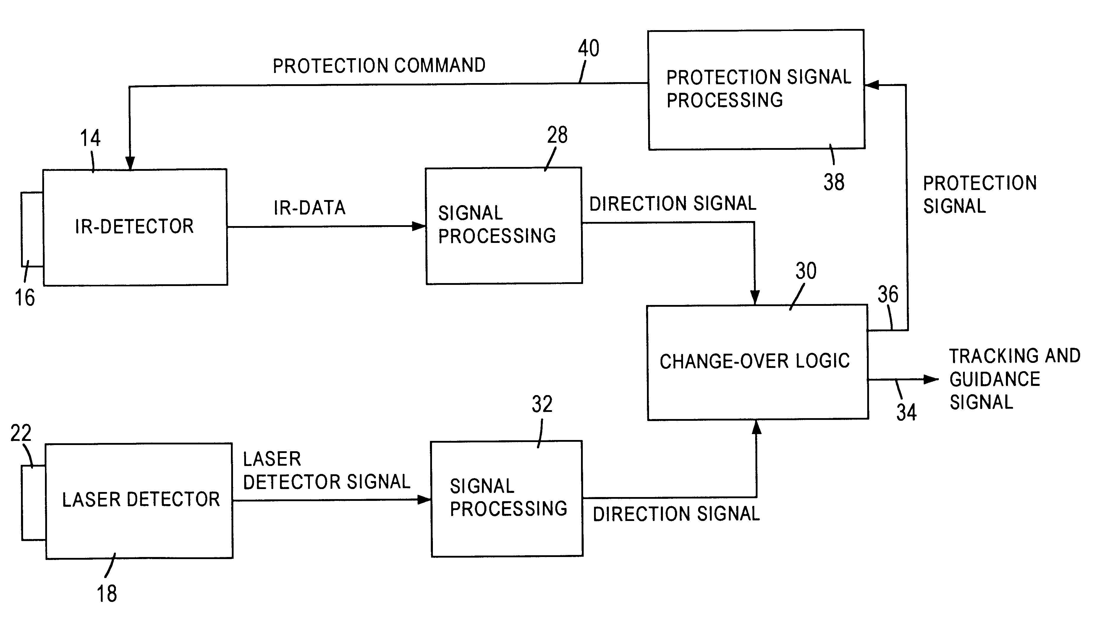
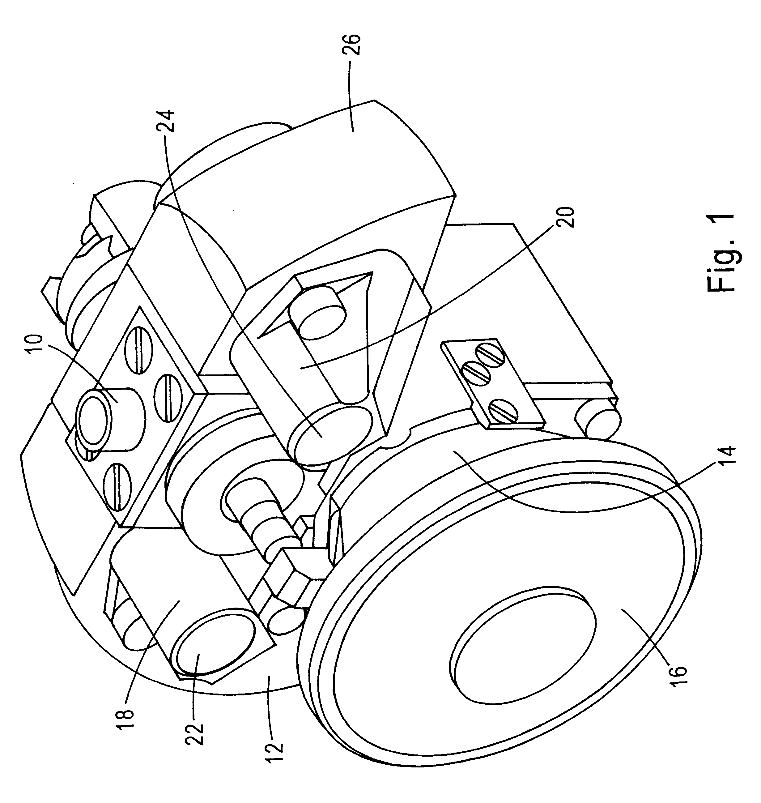
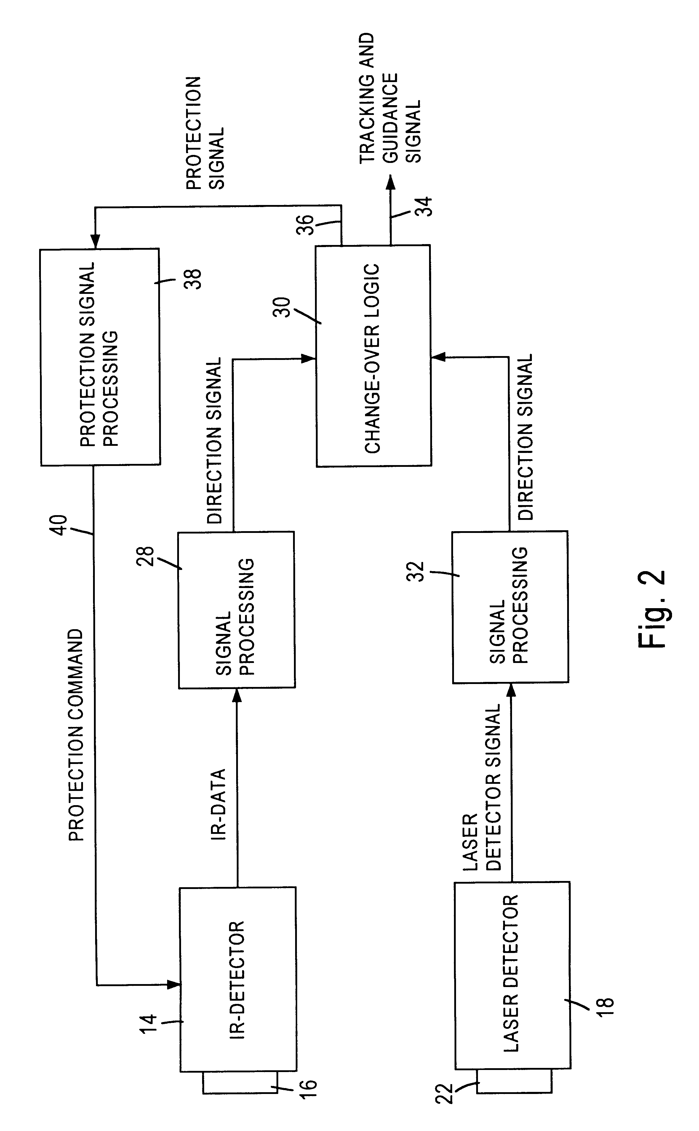
An infrared seeker head is illustrated schematically in FIG. 1. The seeker head may be located in the nose of an air-to-air missile and be protected by a dome which is transparent to infrared radiation. The infrared seeker head is rotatably mounted around an axis 10 on the inner gimbal 12 of a gimbal system. The inner gimbal 12 carries the complete opto-electronical receiver system, the optical axis of which is directed towards the target by rotating the axes of the gimbal system appropriately. A first detector system 14 consists of an infrared optical system 16 as an imaging optical system. This detector system 14 forms a conventional passive infrared detector, which responds to heat radiation. The infrared optical system 16 images a field of view (and the target) on an infrared linear detector array, as main detector, by means of a scanning device arranged behind the optical system and having a movable optical deflection member. The data derived therefrom, is directed further to a...


PUM


Abstract

An infrared seeker head for target tracking missiles has a main detector and an imaging optical system generating an image of a field of view on the main detector. The field of view contains a target such as an enemy aircraft. The missile is guided to the target in accordance with signals from the main detector. The target, if attacked by the missile, emits high-intensity laser radiation towards the missile as a counter-measure. This is to disturb the operation of the seeker head by dazzling or even destroying the main detector. The seeker head contains a device for defending against such disturbances. Various types of such defending devices are described. Incident light is deviated from the main detector. A second-quadrant-detector of reduced sensitivity guides the missile along the disturbing laser beam. Another embodiment uses attenuating optical elements in front of the main detector under the control of one or more second detectors.

Description

The invention relates to an infrared seeker head for target seeking missiles, in which a field of view is imaged, by means of an imaging optical system, on a main detector which detects a target located in the field of view.STATE OF THE ARTThere are manifold prior art infrared seeker heads for missiles.EP patent 0 538 671, for example, discloses an infrared seeker head for target seeking missiles. The seeker head consists of an optical system, which is mounted on an inner gimbal and an outer gimbal and is universally movable relative to a structure. The optical system generates an image of a field of view on a detector. Signals are obtained which cause the seeker to be directed at a target which is detected, by means of two gimbal servomotors.German patent 3,925,942 discloses a gyro-stabilised, seeker. The seeker consists of an imaging optical system, by which a field of view is imaged on a detector. The detector generates target signals, from which direction signals are generated. ...

Claims


Application Information

Patent Timeline
IPC IPC(8): F41G7/22F41G7/20
CPCF41G7/2213F41G7/224F41G7/2253F41G7/2293
Inventor LANKES, SIMONGROSS, MICHAELECKHARDT, REINERHOCH, HEINZ
Owner BODENSEEWERK GERATETECHNIK GMBH
Why Eureka
Try Eureka