Precise instilation eye dropper tip

a technology of eye dropper and tip, which is applied in the field of precise instilation eye dropper tip, can solve the problems of no therapeutic value, no eye dropper, and many individuals who miss the eye altogether

Inactive Publication Date: 2001-03-06
ACU I DROP
View PDF7 Cites 42 Cited by
  • Summary
  • Abstract
  • Description
  • Claims
  • Application Information

AI Technical Summary

Benefits of technology

A primary object of the present invention is to provide a dropper tip that enables

Problems solved by technology

The instillation of medicinal eye drops tends to be difficult and annoying for many individuals.
Often, however, the drop misses the eye altogether and falls on the face, where it has no therapeutic value and may even be irritating to the skin.
Or, several drops might be released if there is a momentary delay in the first drop and a second one is squeezed from the bottle, causing an overdose and waste of medicine.
One can readily see the amount of waste and the poor placement of the falling drop(s) that results.
This may also cause a greater or a lesser dosage of medication to eventually fall into the eye, depending on the size of the drop.
There are several factors that often complicate the conventional way of instilling eye drops.
First, it is difficult for some individuals, especially the elderly, to elevate their shoulder high enough to place the eye dropper in an ideal position above the eye.
Secondly, limitation of motion of the hand or the wrist makes it difficult t

Method used


Image

  • Precise instilation eye dropper tip
  • Precise instilation eye dropper tip
  • Precise instilation eye dropper tip

Examples


Embodiment Construction

, the drawings, and the claims.

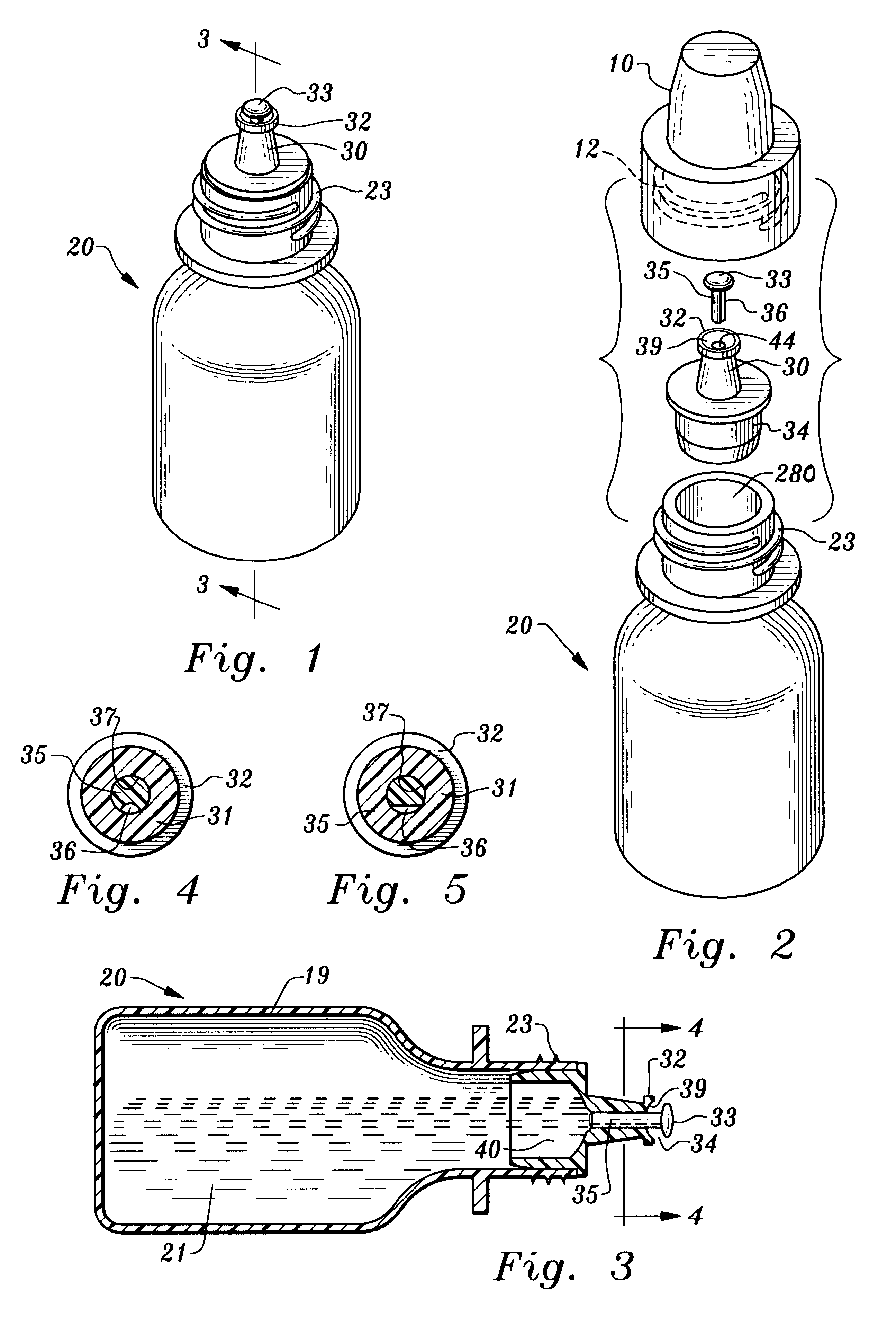
FIG. 1 is a perspective view of an assembled bottle with the present invention.

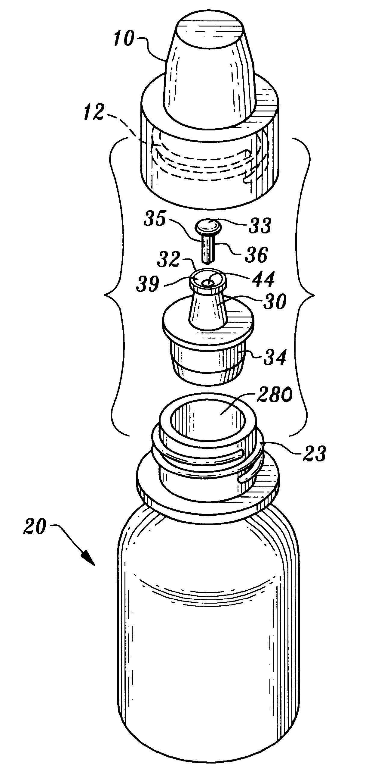
FIG. 2 is an exploded perspective view of a bottle with the present invention.

FIG. 3 is a sectional view 3--3 of FIG. 1 of a bottle with the present invention.

FIG. 4 is a cross sectional view 4--4 of FIG. 3 looking from the reservoir end toward the free end of the tip of the preferred embodiment of the groove of the stem of the present invention.

FIG. 5 is a cross sectional view 4--4 of FIG. 3 looking from the reservoir end toward the free end of the tip of the most preferred embodiment of the groove of the stem of the present invention.

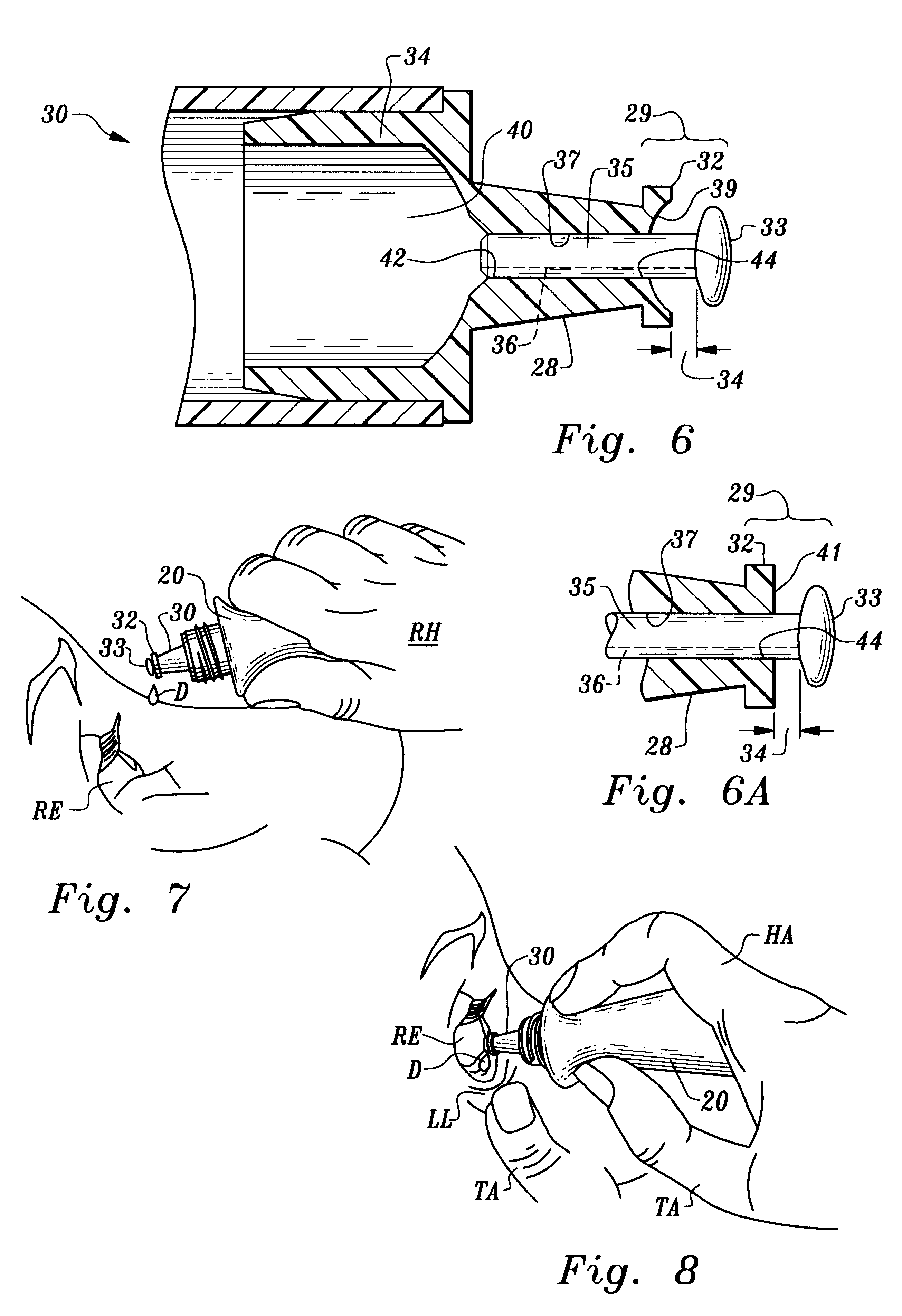
FIG. 6 is a detailed cross sectional view of the present invention.

FIG. 6A is a detailed cross sectional view of the free end of the present invention.

FIG. 7 is a side elevation demonstrating drop instillation into an eye while holding the present invention above and over an opened eye with the head tilted back.

FIG. 8 is a side elevation demon...


PUM


Abstract

A dropper tip 30 is provided which allows a person to instill a drop D into and eye E from a bottle 20 that has compressible and resilient walls 19 while the bottle 20 is held in a horizontal orientation.The dropper tip 30 includes an internal passage 37 into which a stem 35 is inserted. The stem 35 has a groove 36 along its peripheral surface which allows the flow of liquid 21 from the reservoir 20 to the free end 29 of the tip 30. The stem 35 protrudes from the external opening 44 of the internal passage 37 of the tip 30 and has a head 33 on the protruding end. The drop D adheres to the head 33 rather than adhere to and migrate along the external surface 28 of the tip 30.The dropper tip 30 further includes an annulus 32 at the free end 29 of the tip 30 which encircles the external opening 44 of the internal passage 37. The annulus provides a surface for a drop D of liquid 21 to adhere to while awaiting release.The dropper tip 30 further includes a fissure 34 at the free end 29 of the tip 30 which provides an area for drop formation and retention and also acts as a guide to direct the falling drop D into an eye E while the bottle 30 is held horizontally.

Description

This invention relates to an eye dropper tip that enables drops of liquid to fall precisely and consistently from its free end, even if the tip is held in a horizontal orientation, rather than adhere to and migrate along the external surface of the tip.The instillation of medicinal eye drops tends to be difficult and annoying for many individuals. Generally, a person tilts their head back and looks up. Simultaneously, the dropper bottle is elevated above and over the eye and the walls of the bottle are compressed, causing the drop to fall toward the eye.Often, however, the drop misses the eye altogether and falls on the face, where it has no therapeutic value and may even be irritating to the skin. Or, several drops might be released if there is a momentary delay in the first drop and a second one is squeezed from the bottle, causing an overdose and waste of medicine.The standard eye dropper tips that are currently being used, require that the bottle be held in a near vertically dow...

Claims


Application Information

Patent Timeline
IPC IPC(8): A61F9/00B65D47/18B65D47/06
CPCA61F9/0008B65D47/18
Inventor HAGELE, JAMES
Owner ACU I DROP
Why Eureka
Try Eureka