

Military range scoring system
- Summary
- Abstract
- Description
- Claims
- Application Information
AI Technical Summary
Benefits of technology
Problems solved by technology
Method used
Image

Examples
Embodiment Construction
)
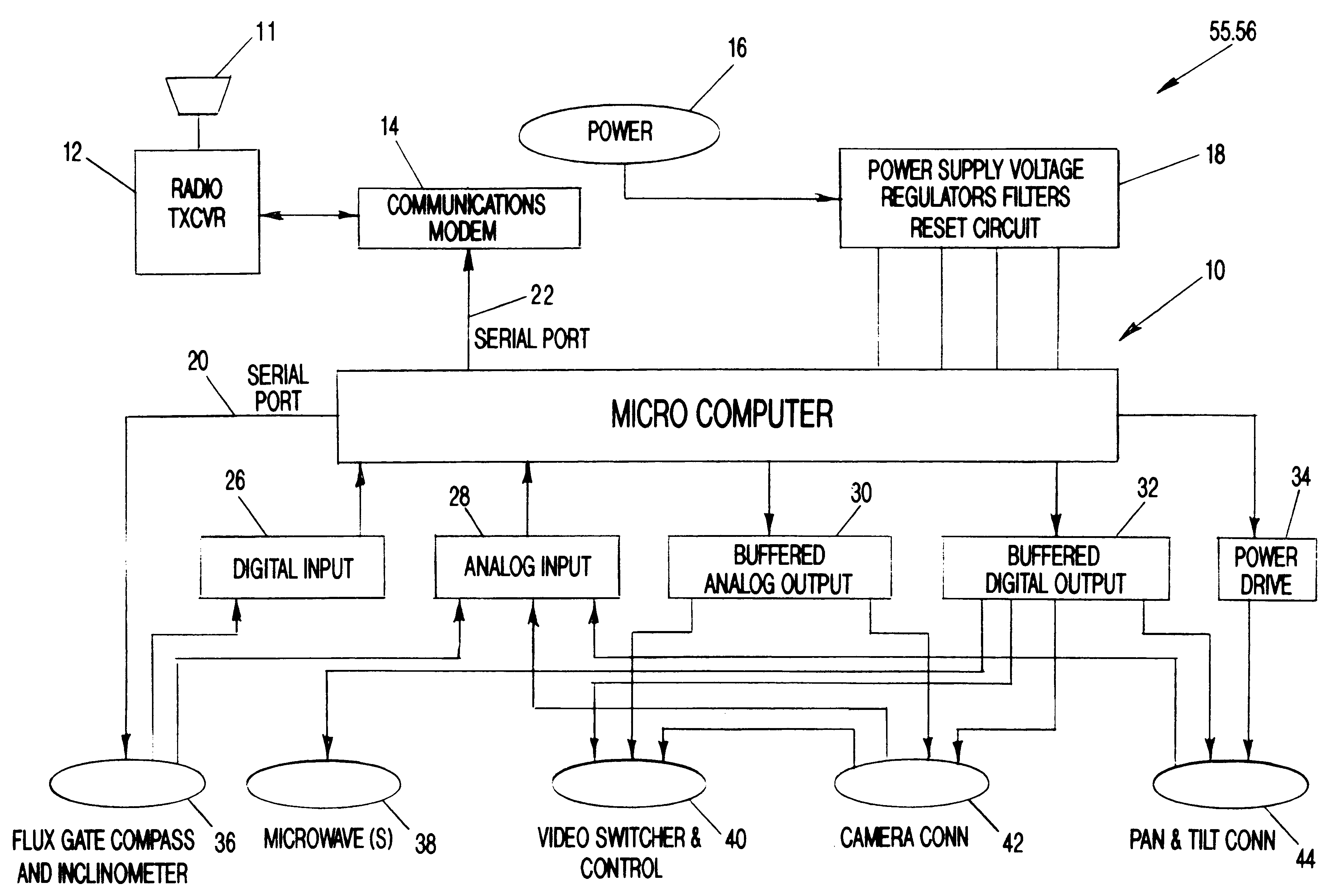
The present invention is of an ordinance scoring system employing, preferably, both optical and thermal imagers which can operate in multiple lighting conditions. The imagers sense visible light, near infrared, infrared, and military laser designators simultaneously with the ability to overlay each onto the others. The output of the sensor is a video-like presentation displaying different energy levels rather than light levels. By sensing the energy levels of each object in the field of view, the imager works as well in the absence of light as it does in visibly bright conditions. Accordingly, the sensor will operate under all day and night ambient conditions and can detect the impact of every type of ordinance now in use as well as a laser spot designator illuminating targets for smart weapons. The sensor can also track the "fly in" path of many weapons that are adequately heated by air resistance during delivery.
The present invention also incorporates a control system which, when...
PUM
 Abstract
Description
Claims
Application Information