Computer system and enclosure thereof

a computer system and enclosure technology, applied in the field of electronic packaging, can solve the problems of high cost of enclosures, affecting the overall cost, and not being able to provide emi shielding very well,

Inactive Publication Date: 2001-03-06
IBM CORP
View PDF12 Cites 108 Cited by
  • Summary
  • Abstract
  • Description
  • Claims
  • Application Information

AI Technical Summary

Problems solved by technology

The enclosures are usually expensive due to high cost for the mechanical components and labor costs for manually assembling them.
Moreover, the appearances are...

Method used


Image

  • Computer system and enclosure thereof
  • Computer system and enclosure thereof
  • Computer system and enclosure thereof

Examples


Embodiment Construction

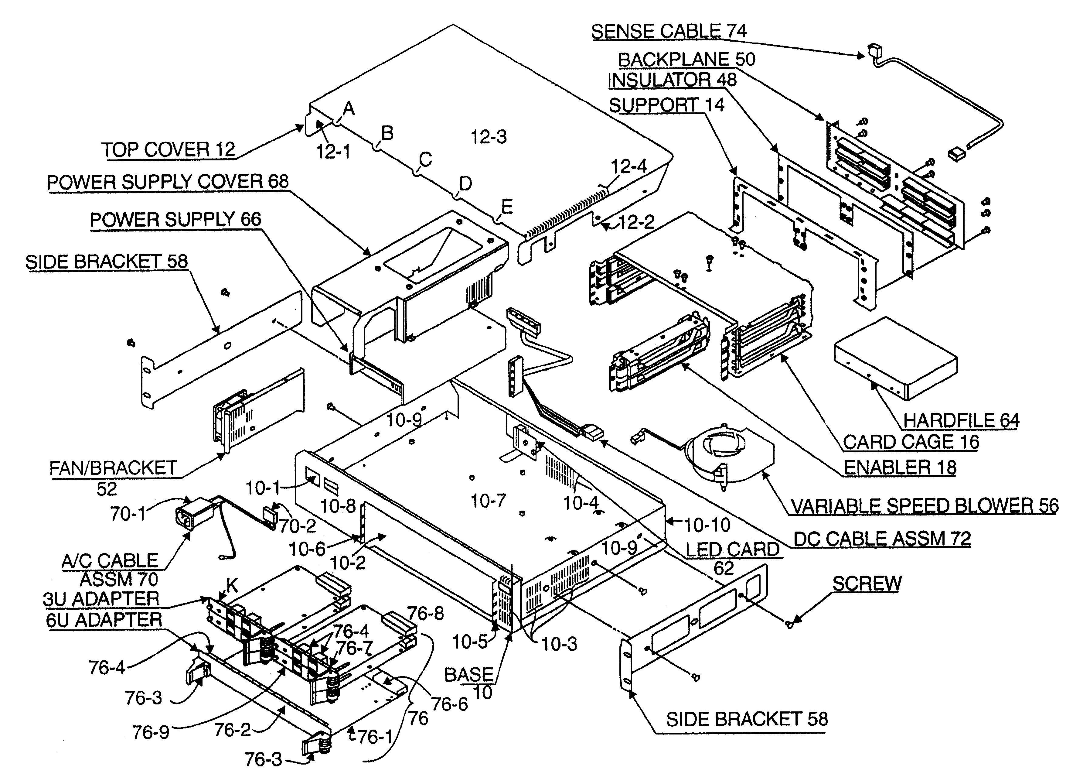
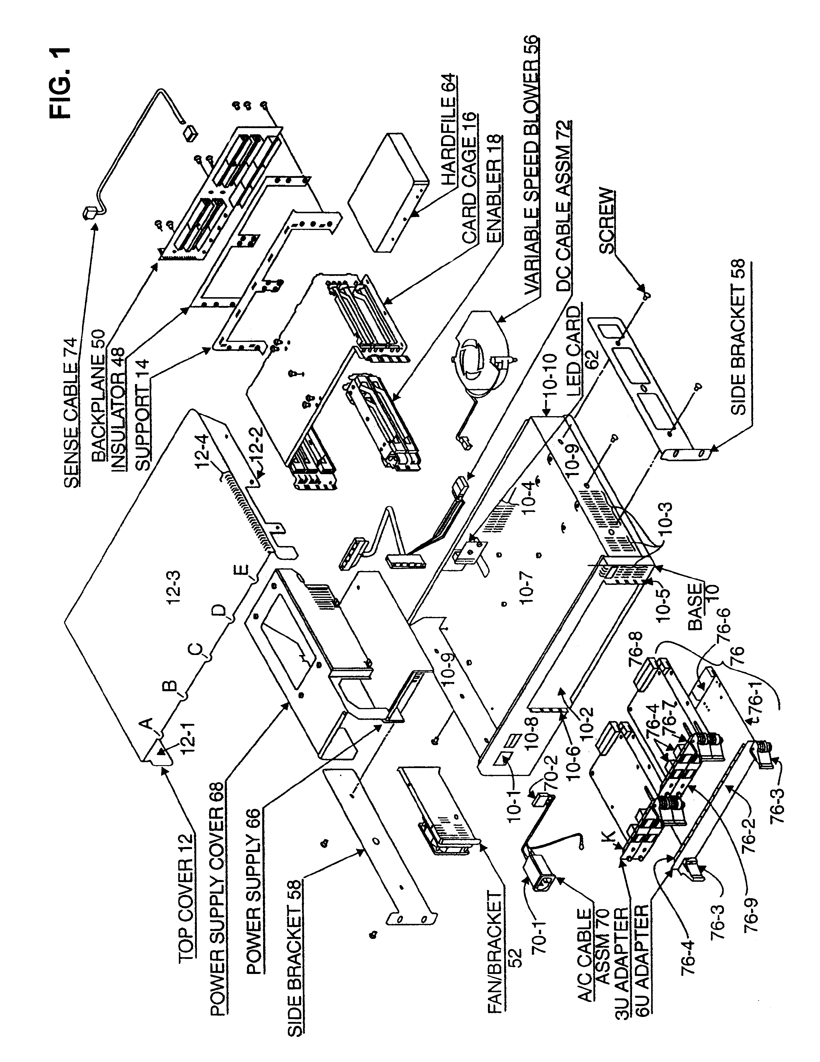
FIG. 1 shows an exploded view of the electrical machine according to the teachings of the present invention. The electrical machine could be a bridge, router, hub, or any of the well-known interconnecting devices used in networking technology. The electrical machine includes a housing or enclosure, internal components, electrical components, EMC Shielding system, electrical grounding system and mounting system which mounts the electrical machine in a rack.

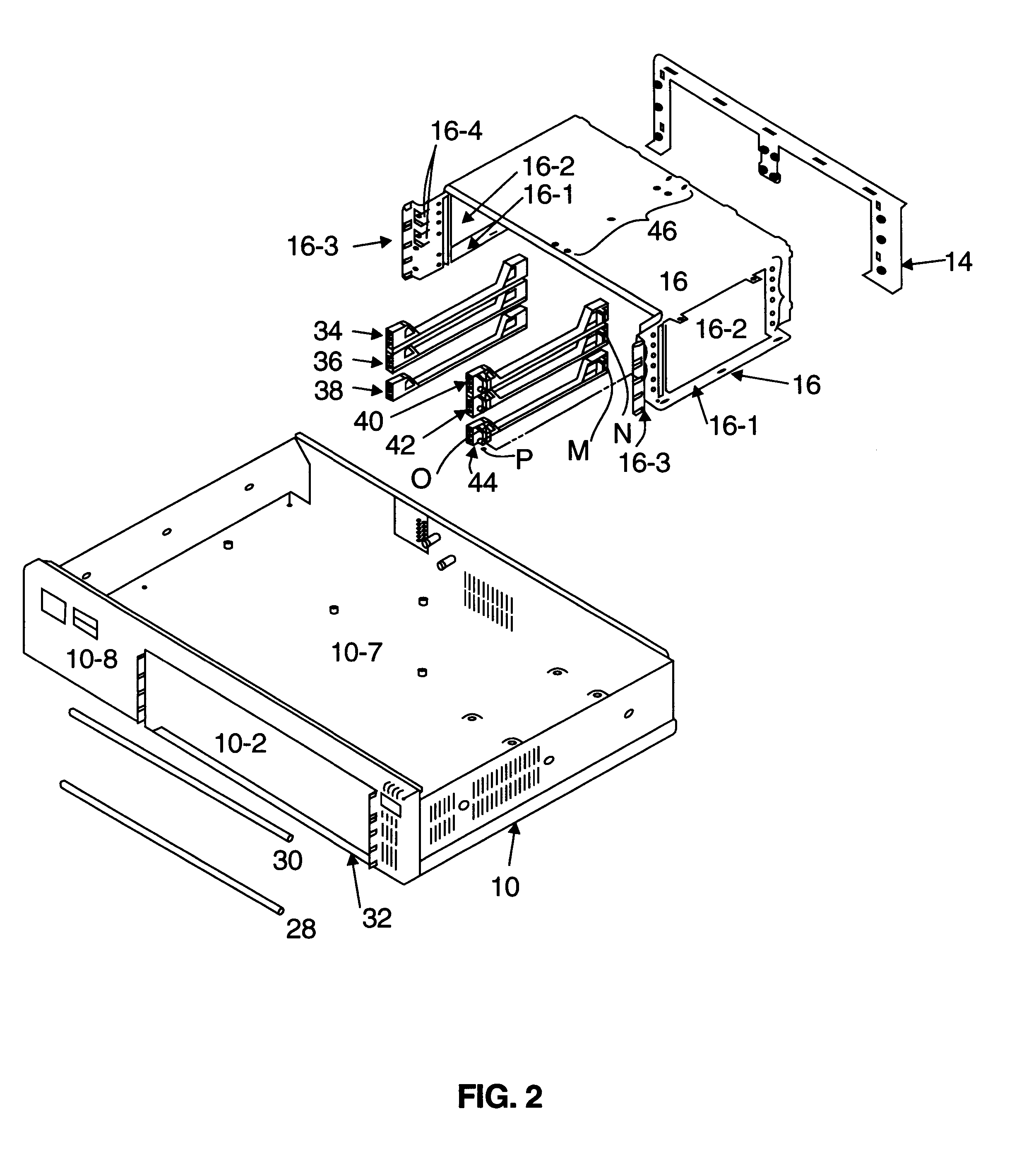
The housing includes Base 10, Top Cover 12, Support 14, Card Cage 16 and Enabler 18. The Base 10 is fabricated from a single piece of material (i.e., sheet metal) in which multiple design details are placed. The single piece of material with the design details is then formed into a desired mechanical structure. With reference to FIG. 1, the multiple design details include Openings 10-1 and 10-2, Air Inlet Slots 10-3, Air Outlet (exhaust) Slots 10-4, holes for receiving fasteners, Vertical Flanges 10-5 and 10-6, etc. The Opening 10-...


PUM


Abstract

The enclosure includes a base section fabricated from a single piece of material, such as sheet metal, in which multiple design details are punched and formed. A cover section with tabs for inserting in slots formed in the base section is provided. A one-piece card cage including injector/ejector latching details and card guide rails is connected via welding or other means to the base section. An enabler assembly, including guide rails, is fastened to the card cage and configures the card cage into multiple adapter receiving cavities.

Description

Cross Reference to Related Patent ApplicationThe present patent application relates to patent application Ser. No. 60 / 080,280, filed on Apr. 1, 1998. filed currently herewith and assigned to the assignee of the present invention.Field of the InventionThe present invention relates to electronic packaging in general and, in particular, to electronic packaging of Personal Computers (PC) and other network interconnecting devices.Prior ArtPersonal computers and network interconnecting devices such as routers, concentrators, etc. typically have an enclosure in which several components are mounted. Typical components include blowers, hard disk, motherboard, circuit cards, etc. Most of the designs are roll-your-own in that each manufacturer designs its machines to its own liking without regard for interchangeability of parts from other manufacturers. Examples of prior art machines are set forth in U.S. Pat. Nos. 4,916,578; 5,175,669; 5,218,514; 5,519,573; 5,596,483 and 5,600,538.U.S. Pat. N...

Claims


Application Information

Patent Timeline
IPC IPC(8): G06F1/18
CPCG06F1/18G06F1/184G06F1/185G06F1/186
Inventor LEHMAN, BRET W.MILES, ANTHONY WAYNE
Owner IBM CORP
Why Eureka
Try Eureka