
Dilution refrigerator

Inactive Publication Date: 2001-03-20
OXFORD INSTR NANOTECH TOOLS
View PDF2 Cites 9 Cited by
  • Summary
  • Abstract
  • Description
  • Claims
  • Application Information

AI Technical Summary

Problems solved by technology

The problem with top loading into the mixing chamber is that it is necessary to provide a clear access tube into the mixing chamber.
However, even with a displacer, there is a significant heat leak through the liquid around the displacer and this limits the base temperature.
A problem with the system of Pavlov is that a film of superfluid .sup.4 He will flow up the pumping line due to the temperature gradient (since superfluid .sup.4 He flows from low temperature regions to high temperature regions).
The evaporation of .sup.4 He impairs the cooling efficiency of the refrigerator and as a result a very powerful pump must be used.
However this would then limit the diameter of the probe (since the probe must be passed down the pumping line into the still).
However this increases the fluid impedance of the pumping path which can result in a more powerful pump being required.

Method used


Image

  • Dilution refrigerator
  • Dilution refrigerator
  • Dilution refrigerator

Examples


Embodiment Construction

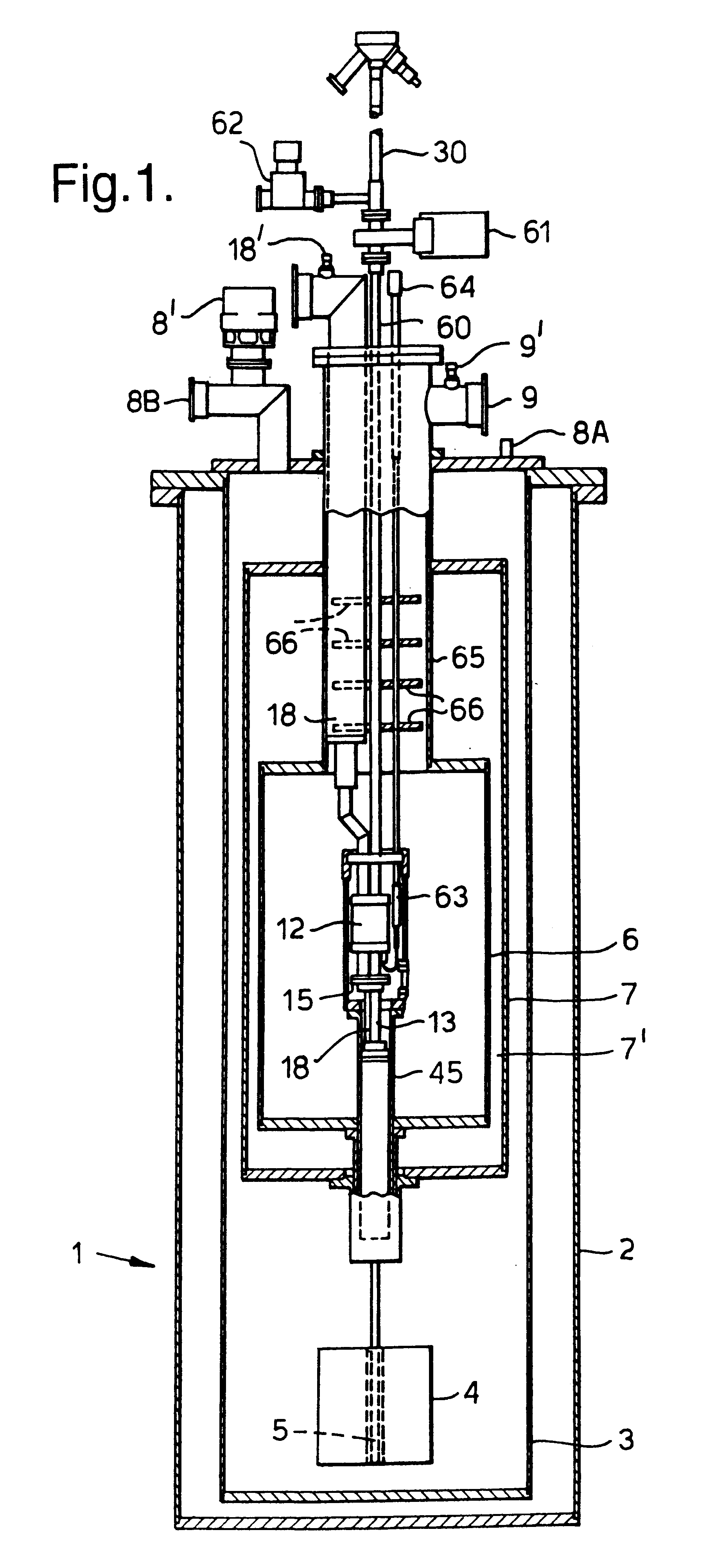
The apparatus shown in FIG. 1 comprises a cryostat 1 having a cylindrical outer wall 2, radially inwardly of which is mounted a cylindrical wall 3 with a vacuum defined in the space between the walls 2,3. The wall 3 defines a chamber filled with liquid nitrogen and containing a magnet 4 having a bore 5. Axially positioned above the magnet 4 within the liquid nitrogen reservoir is a cylindrical liquid helium reservoir 6 separated from the liquid nitrogen reservoir by an evacuated region 7' defined between the reservoir 6 and a wall 7. An inner vacuum vessel 45 is positioned within the reservoir 6. Conventional ports 8A,8B are coupled with the liquid nitrogen reservoir for supplying and exhausting nitrogen respectively and similar ports 9 (only one shown) are provided for the helium reservoir 6. Each port 8B and 9 has an associated pressure relief valve 8', 9' respectively.

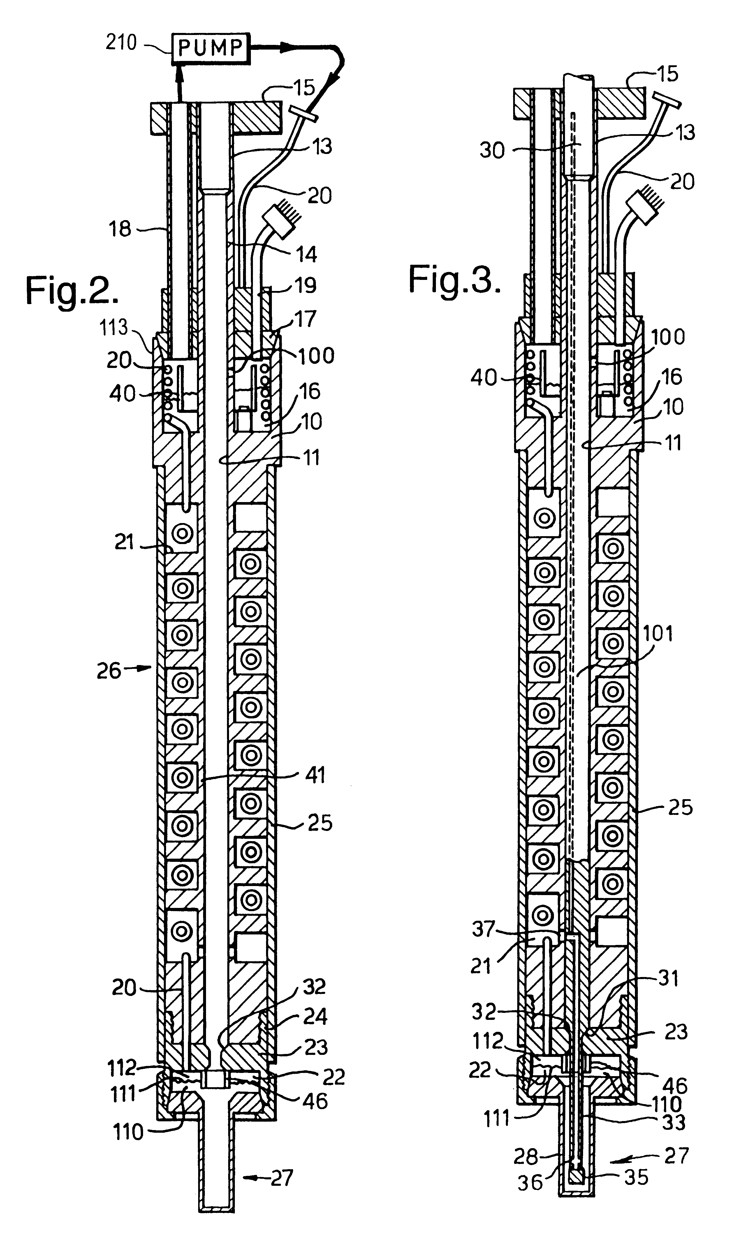
A dilution refrigerator is inserted along a central axis of the cryostat 1. The dilution refrigerator is generall...


PUM


Abstract

A dilution refrigerator includes a still; a mixing chamber; a pump to pump coolant from the still through a still outlet port and a heat exchanger connected between the still and mixing chamber whereby coolant flows under the assistance of the pump from the still to the mixing chamber and from the mixing chamber to the still through respective first and second adjacent paths in the heat exchanger. An access path extends to the mixing chamber. A probe is provided for insertion along the access path, the probe having a displacer which substantially fills the cross-section of the access path in use. Any coolant from the mixing chamber which flows along the access path past the displacer can flow from the access path into the still. The still outlet port is separate from the access path.

Description

The invention relates to a dilution refrigerator.DESCRIPTION OF THE PRIOR ARTDilution refrigerators are used for achieving ultra low temperatures for experiments in the millikelvin temperature range. A typical dilution refrigerator includes a still, a mixing chamber, and a heat exchanger connected between the still and mixing chamber whereby coolant flows from the still to the mixing chamber and from the mixing chamber to the still through respective first and second adjacent paths in the heat exchanger. Examples of known dilution refrigerators are described in U.S. Pat. No. 5,189,880, "A Simple Dilution Refrigerator" by J. L. Levine, The Review of Scientific Instruments, Vol. 43, Number 2, February 1972, pages 274-277, "Fully portable, highly flexible dilution refrigerator systems for neutron scattering", Hilton et al, Revue de Physique Appliquee, Vol. 19, No. 9, pages 775-777, and GB-A-2166535.Typically, such a dilution refrigerator uses .sup.3 He / .sup.4 He and makes use of the fa...

Claims


Application Information

Patent Timeline
IPC IPC(8): F25B9/12
CPCF25B9/12
Inventor MIKHEEV, VLADIMIR ANDREYEVICHWHITE, JEREMY PHILIPFOSTER, TIMOTHY JOHNBATEY, GRAHAM JOHN
Owner OXFORD INSTR NANOTECH TOOLS
Learn More