Method and apparatus for holding paper currency and credit cards

a technology for paper currency and credit cards, applied in the field of money clips, can solve the problems of permanent deformation of money clips, inability to hold smaller sizes and thicknesses of money, and inability to teach or sugges

Inactive Publication Date: 2001-03-27
ODISHOO PERA M
View PDF23 Cites 20 Cited by
  • Summary
  • Abstract
  • Description
  • Claims
  • Application Information

AI Technical Summary

Benefits of technology

The two rows of members are separated into an outer row and an inner row. Each member of the outer row is connected through two links to two corresponding members on the inner row. Likewise, each member of the inner row is connected through two links to two corresponding members on the outer row. The links permit the members of the outer row and the members of the inner row to expand in a longitudinal direction away from its adjacent member to receive and hold the inserted money. The links also allow the continuous band to be turned around so that either of the two rows of members can become the exposed surface. Thus, the continuous band is reversible.

Problems solved by technology

Although Applicant's invention uses a linkage design like those disclosed in the issued patents, the prior art does not teach or suggest that such a linkage design is useful as a money holder.
Furthermore, if the ends of the money clip are spread apart too far, the money clip is permanently deformed making it unusable to hold smaller sizes and thicknesses of money.
Another shortcoming is that this money clip is susceptible to breaking at its midpoint if the folded ends are displaced far enough from one another.
Another shortcoming is that a portion of the money remains exposed and not completely secured within the money clip and, therefore, the money is vulnerable to undesired removal from the money clip.
A shortcoming of this carrying device is that the band has a weakness where the free ends of the band are fastened.
As a consequence, the band is susceptible to easy breaking after continued use or wear and tear.
Furthermore, the band may not slide easily into the user's pocket due to friction between the band and the cloth pocket.

Method used


Image

  • Method and apparatus for holding paper currency and credit cards
  • Method and apparatus for holding paper currency and credit cards
  • Method and apparatus for holding paper currency and credit cards

Examples


Embodiment Construction

will be better understood with reference to the following figures:

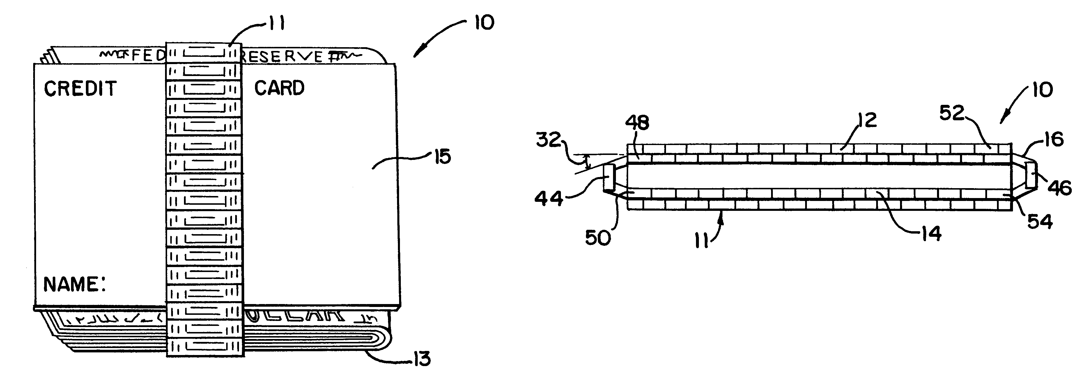
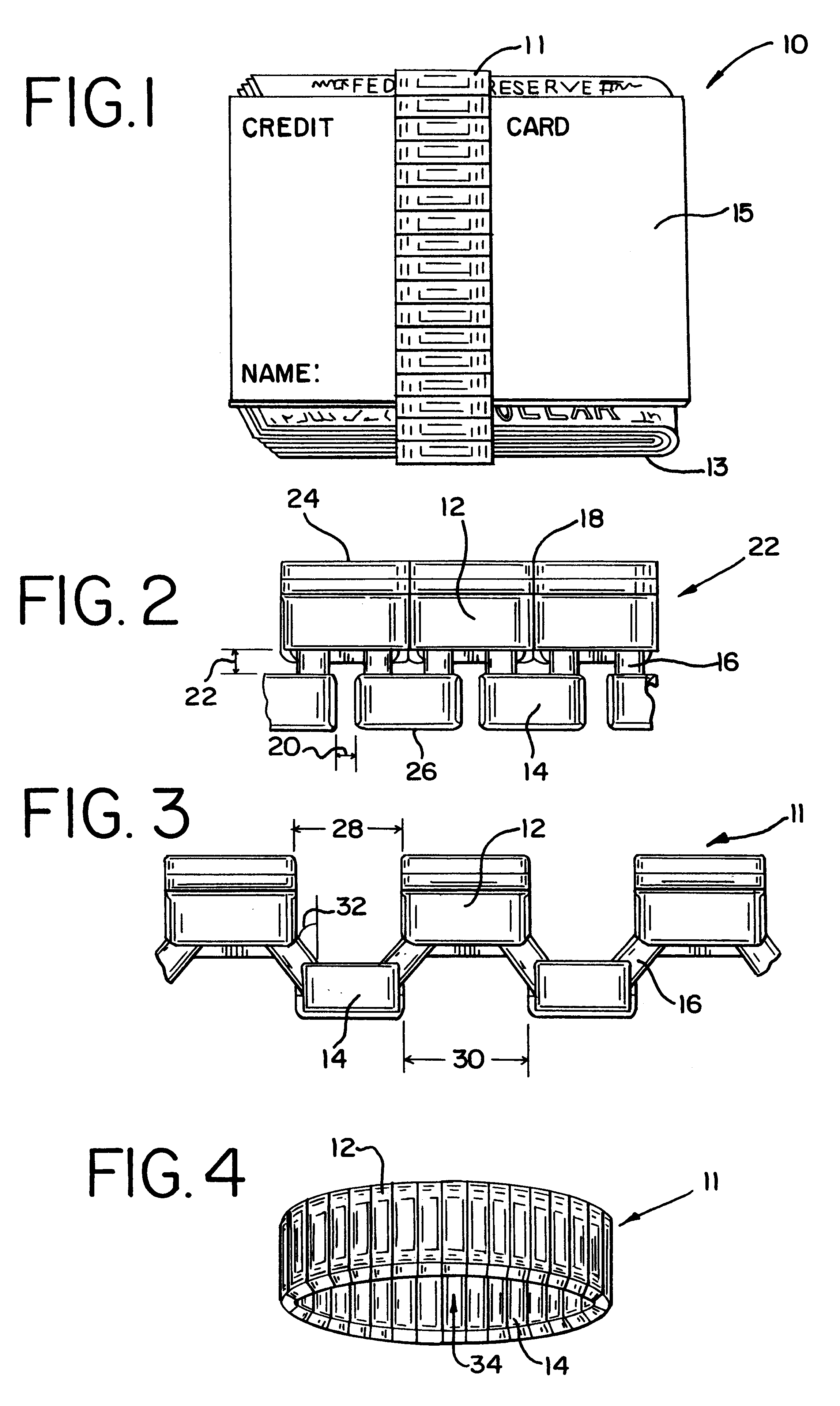
FIG. 1 is a perspective view of applicant's band holding paper currency and a credit card.

FIG. 2 is a side view, with portions removed, of a section of a prior art bracelet illustrating the members of the inner and outer rows interlinked together in a closed flat configuration.

FIG. 3 is a side view, with portions removed, of a section of a prior art bracelet illustrating the members of the inner and outer rows as interlinked together in an expanded flat configuration.

FIG. 4 is a perspective view of a money clip band with the outer and inner members in a continuous uninterrupted loop.

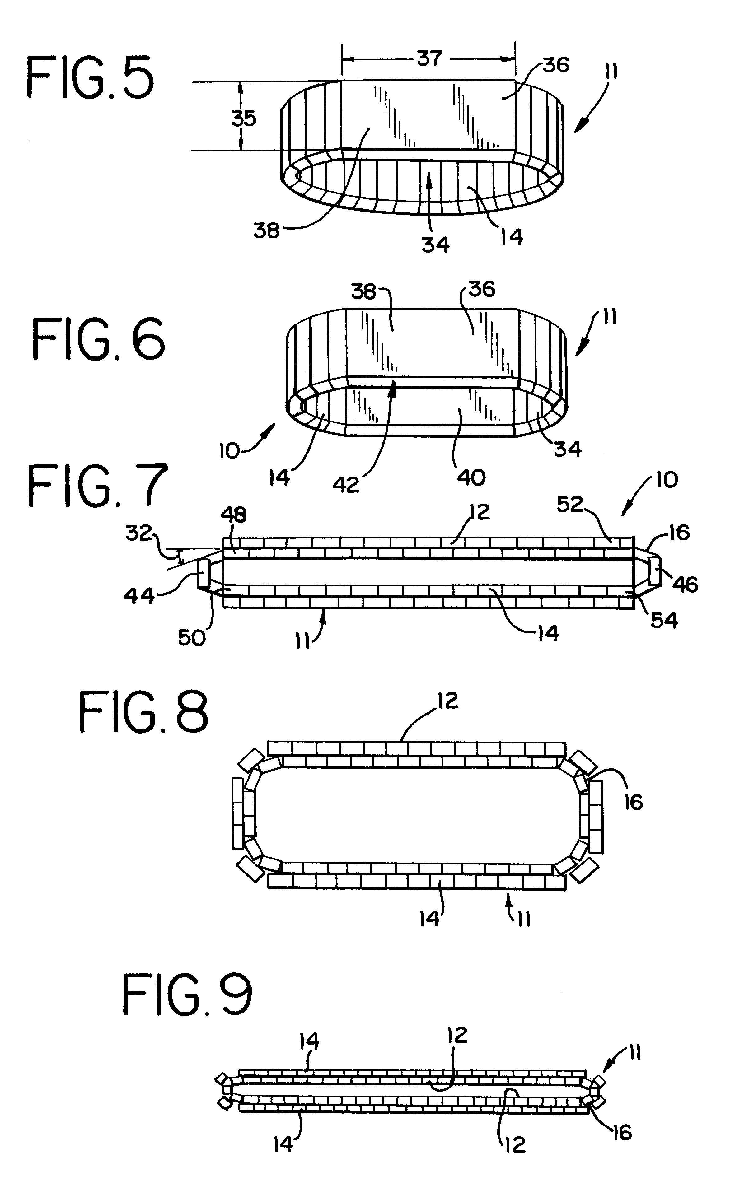
FIG. 5 is a perspective view of a money clip band with the outer and inner members in a continuous loop separated by an extended length link.

FIG. 6 is a perspective view of a money clip band with the outer and inner members in a continuous loop separated by two opposed solid extended length links.

FIG. 7 is a side view of the money clip of ...


PUM


Abstract

A method for holding money and money clip or band designed to efficiently accommodate and hold all amounts and quantities of paper currency. The money clip uses a continuous row of outer members and a continuous row of inner members that are interconnected through a linkage system that provides for the longitudinal displacement of the outer members and inner members relative to one another to receive and hold the paper currency inserted. The band is very sturdy and flexible to provide for reversibility in that it may be rotated 180 degrees so that either side may be used as the exposed outer display surface. The exposed outer display surface is presented with an attractive display.

Description

I. FIELD OF THE INVENTIONThe present invention relates to money clips and, more particularly, to an expansion band that provides two rows of continuous members that are interlinked to provide longitudinal displacement of the links relative to one another to receive and hold various amounts of money, such as paper currency and credit cards.II. DESCRIPTION OF THE PRIOR ARTIn the past two adjacent rows of interlinked members have been used as a bracelet for watches to permit the bracelet to expand to receive a person's hand and then contract to surround the person's wrist to support the watch.Various types of linkage designs have been used in expandible bracelets for watches and are disclosed in U.S. Pat. No. 4,723,406 to Ripley entitled "Expansible Linkage For Use In Making a Watchband or Similar Article"; U.S. Pat. No. 4,096,688 to Rieth entitled "Expansible Linkage For Wrist Watch Bracelets, Identification Bracelets and The Like"; U.S. Pat. No. 3,786,629 to Rieth entitled "Expansibl...

Claims


Application Information

Patent Timeline
Patent Type & Authority Patents(United States)
IPC IPC(8): A45C1/00A45C1/06A45C11/18A44C5/04A44B99/00A44C5/08A45F5/00
CPCA44C5/08A45C1/06Y10T24/1406Y10T24/1408A45C11/182
Inventor ODISHOO, PERA M.
Owner ODISHOO PERA M
Why Eureka
Try Eureka