Engine balance shafts supporting structure

a technology of supporting structure and balance shaft, which is applied in the direction of machines/engines, mechanical equipment, vibration suppression adjustments, etc., can solve the problems of deteriorating workability, partial wear, and reducing the number of components and assembling man hours

Inactive Publication Date: 2001-03-27
HONDA MOTOR CO LTD
View PDF3 Cites 46 Cited by
  • Summary
  • Abstract
  • Description
  • Claims
  • Application Information

AI Technical Summary

Problems solved by technology

To cope with this, it is considered that a casing as described above and bearings for the balance shafts are divided in two halves in vertical directions, but when the entirety of the balancer is constructed to be so divided, an oil pump body cannot be molded integrally with the casing and therefore it has to be retrofitted, this leading to a drawback of increasing the number of components and assembling man hours.
On the other hand, it is possible that two casing halves including an oil pump body and an oil pump cap are subassembled and that thereafter mounting surfaces to the cylinder block of such a sub-assembly are processed, but this deteriorates the workability.
Therefore, it is desirable that a mounting surface of each component to the cylinder block be processed, but this tends to cause processing errors and in a worse case, the balance shafts incline and this causes partial wear.

Method used


Image

  • Engine balance shafts supporting structure
  • Engine balance shafts supporting structure
  • Engine balance shafts supporting structure

Examples


Embodiment Construction

Referring to the accompanying drawings, a preferred mode of implementation of the present invention will be described in detail below.

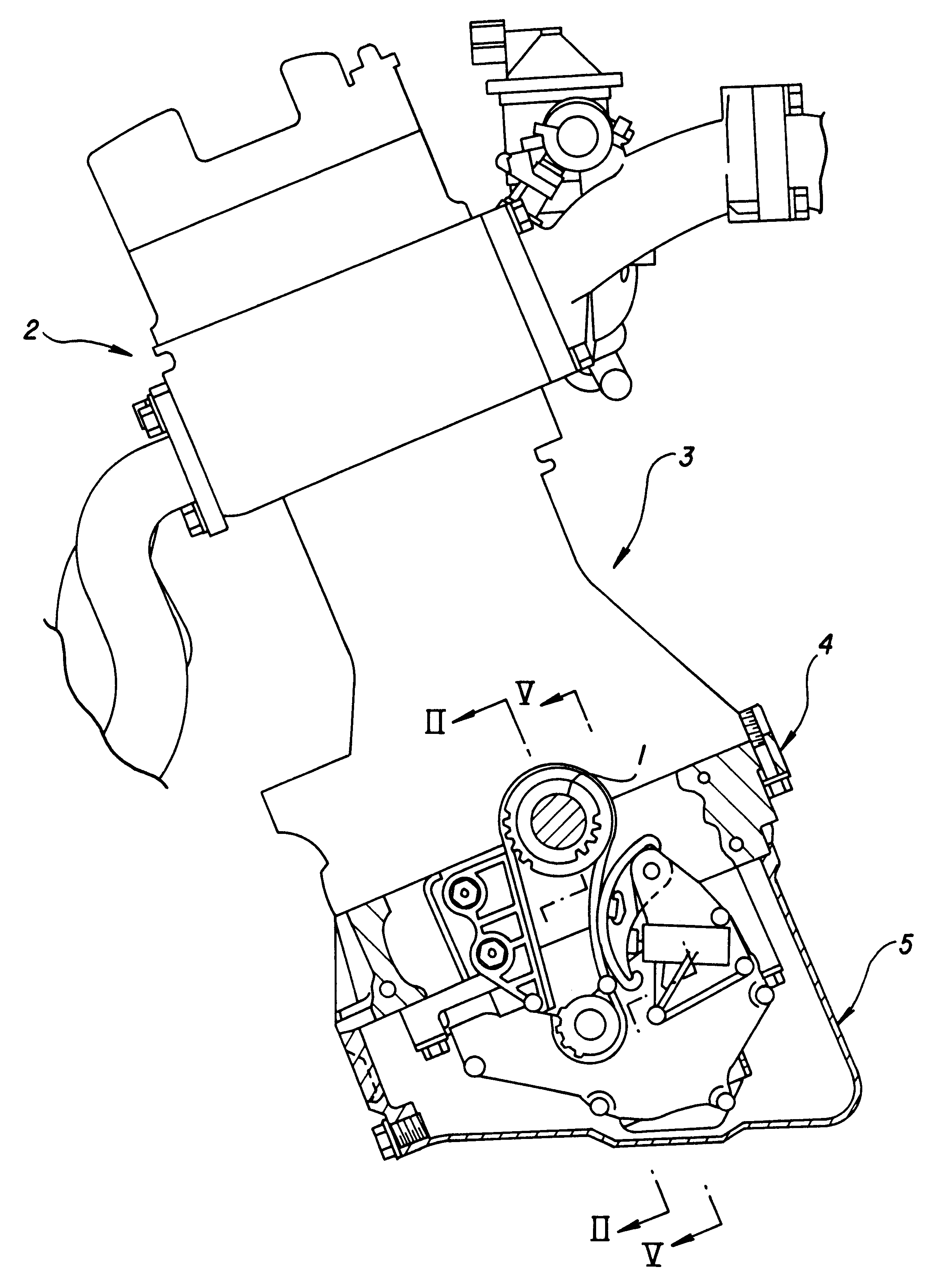
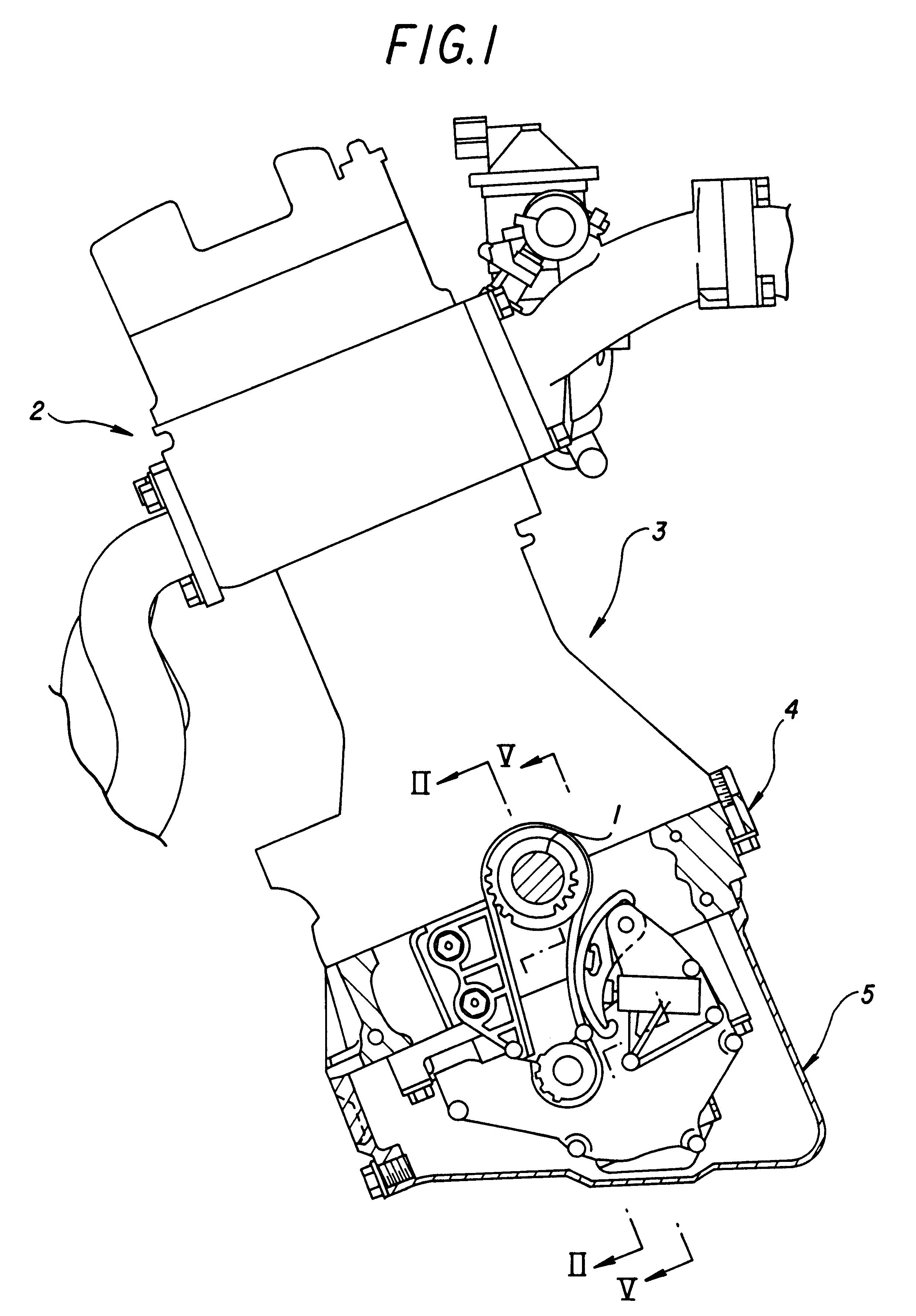
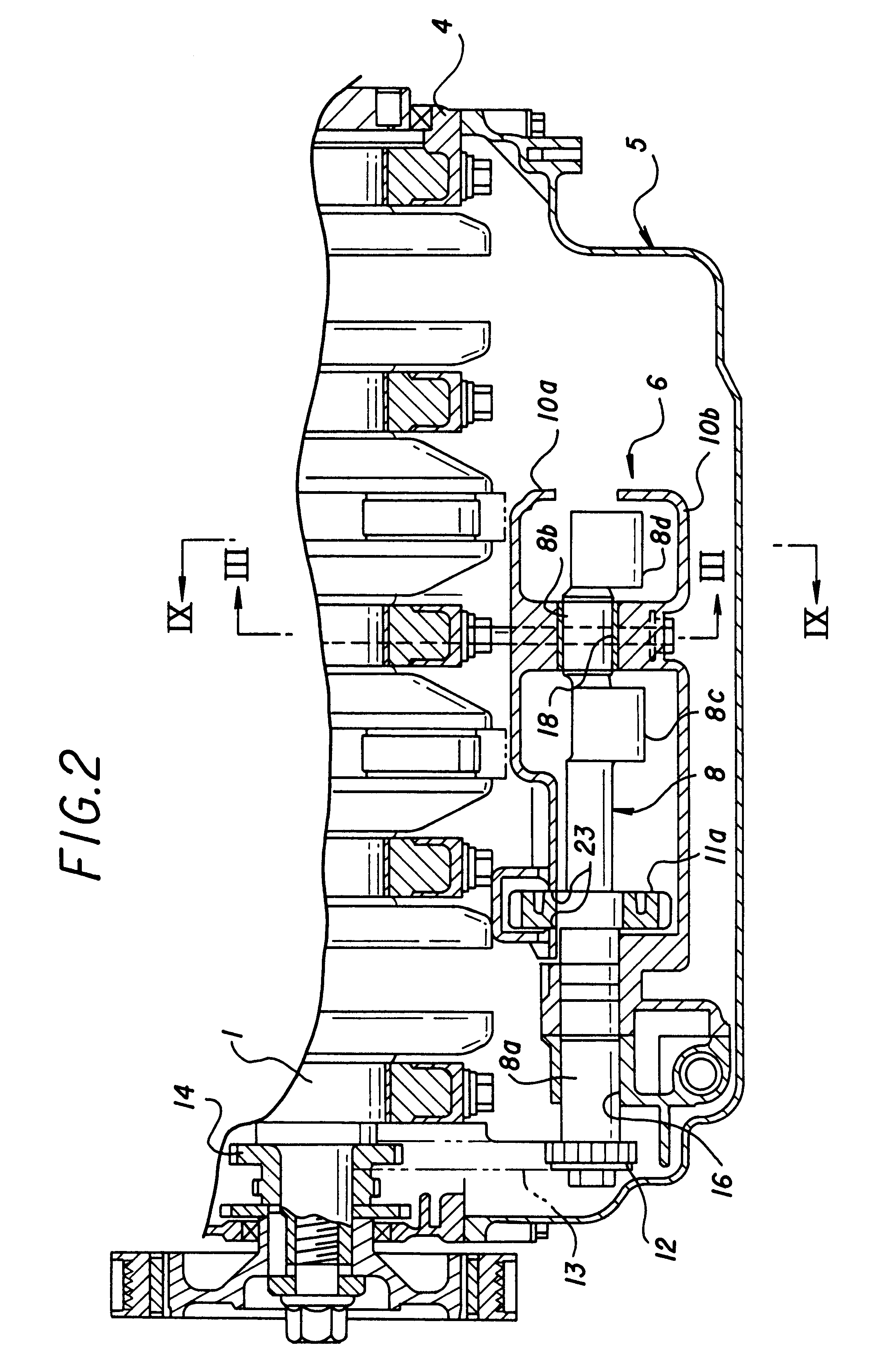
FIG. 1 is a vertical sectional view of a main part of an engine, and FIG. 2 is a sectional view taken along the line II--II of FIG. 1. An engine E is an in-line four-cylinder engine in which four cylinders are disposed substantially in a perpendicular direction and in which a crankshaft 1 is disposed in a horizontal direction. A main body of the engine comprises a cylinder head 2, a cylinder block 3 connected to a lower surface of the cylinder head, a lower block connected to a lower surface of the cylinder block 3 and an oil pan 5 connected to a lower surface of the lower block 4. A journal portion of the crankshaft 1 is rotatably supported on a bearing formed between the cylinder block 3 and the lower block in such a manner as to be split into two halves.

A secondary balancer device 6 for reducing secondary vibrations and an oil pump 7 comprising a t...


PUM


Abstract

A casing accommodating therein a pair of balance shafts below the cylinder block comprises an upper casing and a lower casing that can vertically be split, and an oil pump body is molded integrally with one of the upper and lower casings. In addition, one end of each of the two casings is inserted into the oil pump body for support therein, and the two balance shafts are each supported on a bearing provided between the two casings in such a manner as to be split into two halves at an intermediate portion or the other end thereof. With this construction, the oil pump body can be molded together with the casing, thereby making it possible to reduce the number of components used and man hours for assembling. In addition, since the bearings can be split into two halves, when compared with other portions of the balance shafts, the journal portion can be thinned, thereby making it possible not only to reduce the sliding friction but also to make the casing smaller in size and lighter in weight. More over, the degree of freedom of designing balance shafts can also be improved. With the balance shaft supporting structure for an engine the durability of a balancer, as well as the degree of freedom of designing the same are improvided without making the engine larger in size and increasing the number of components used.

Description

1. Field of the InventionThe present invention relates to an engine having balance shafts disposed below a cylinder block, and more particularly to a supporting structure for the balance shafts of the engine.2. Description of the Related ArtThere have been existing heretofore engines having a balancer below the cylinder block (for instance, refer to the Japanese Patent Unexamined Publication (Kokai) No. Sho. 63-106443). In an engine of this type, the balancer comprises a pair of balance shafts supported on a casing disposed in an oil pan below the cylinder block. The balance shafts are intermeshed with each other, and the driving force of a crank shafts is transmitted therefrom to one of the balance shafts via a chain or the like, whereby the two balance shafts are rotated at twice the crankshaft revolution speed in opposite directions.On the other hand, in the above construction, an oil pump is also disposed below the engine closer to the balancer with a view to making it smaller. ...

Claims


Application Information

Patent Timeline
Patent Type & Authority Patents(United States)
IPC IPC(8): F02B75/20F02B75/00F16F15/22F16F15/26
CPCF02B75/20F16F15/26F16F15/264F01M2001/0276
Inventor IWATA, KAZUYUKINIIZATO, TOMONORI
Owner HONDA MOTOR CO LTD
Why Eureka
Try Eureka