Seal for pump

A technology for piston seals and sealing parts, which is used in pump components, engine seals, variable-capacity pump parts, etc. Effect

Inactive Publication Date: 2007-04-25
NOK CORP
View PDF2 Cites 27 Cited by
  • Summary
  • Abstract
  • Description
  • Claims
  • Application Information

AI Technical Summary

Problems solved by technology

However, if the material of the fuel seal lip 101 is changed to a resin such as PTFE, the shape of the seal lip 101, that is, the angles α and β, are deformed and changed due to the creep charact

Method used


Image

  • Seal for pump
  • Seal for pump
  • Seal for pump

Examples


no. 1 Embodiment

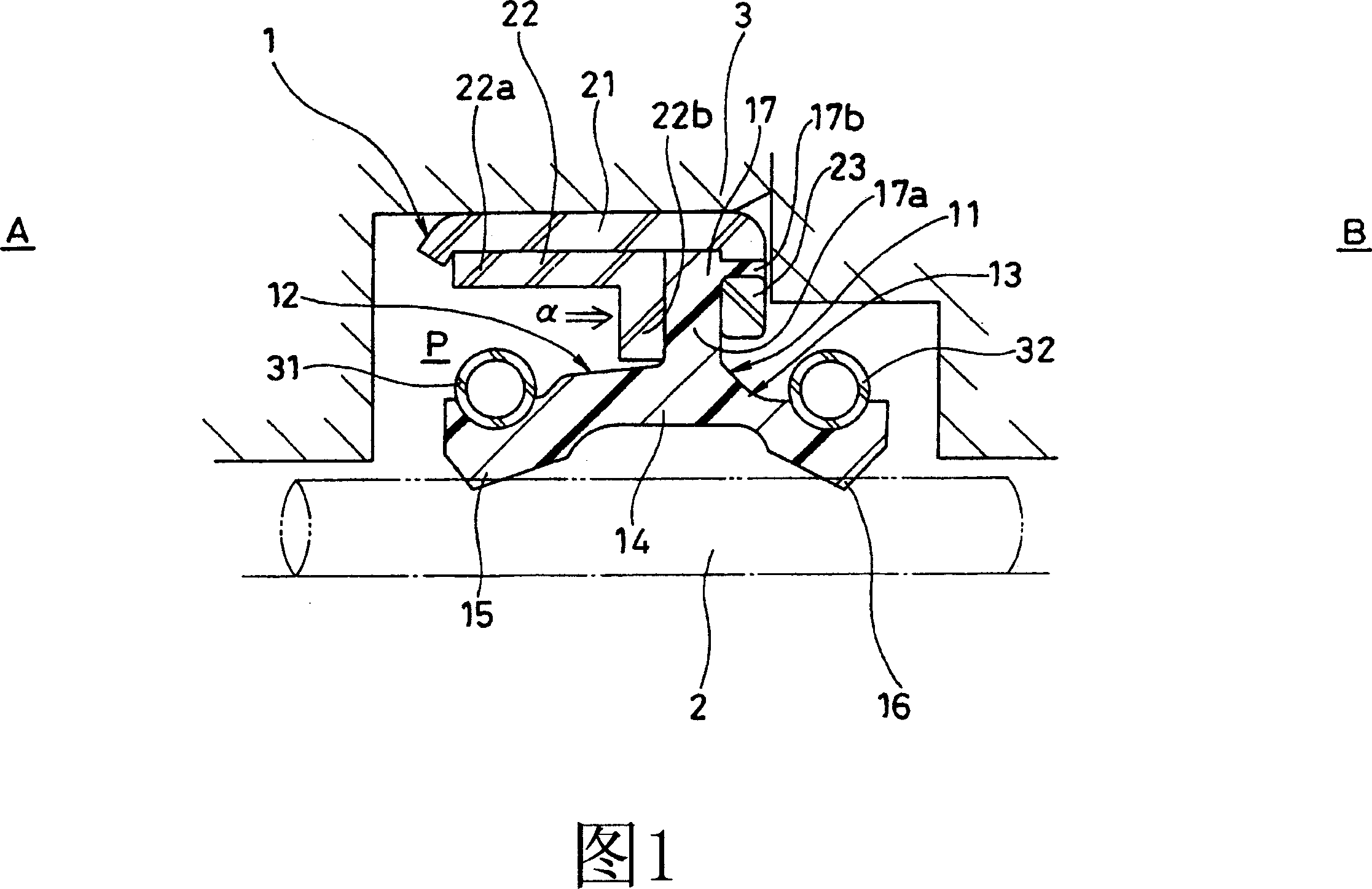
1 is a cross-sectional view of a pump piston seal 1 according to a first embodiment of the present invention installed in an annular space formed by a piston 2 and a housing 3 which are shafts reciprocating in a high-pressure fuel injection pump.

[0025] The pump piston seal 1 is used in fuel injection pumps for gasoline direct injection engines. It has the function of sealing gasoline and other fuels under high pressure on the side of the sealing object, and it is used for cooling or lubricating on the side of the anti-sealing object. Oil seal function.

[0026] In FIG. 1, the pump piston seal 1 consists of a sealing member 11; three metal rings 21, 22, 23 holding the sealing member 11; The two coil springs 31, 32 of the two sealing lips 15, 16 are formed.

[0027] The three metal rings 21, 22, 23 consist of a first metal ring 21 fitted on the inner peripheral side of the housing 3, a cylindrical portion 22a fitted on the inner peripheral side of the first metal ring 21, and...

no. 2 Embodiment

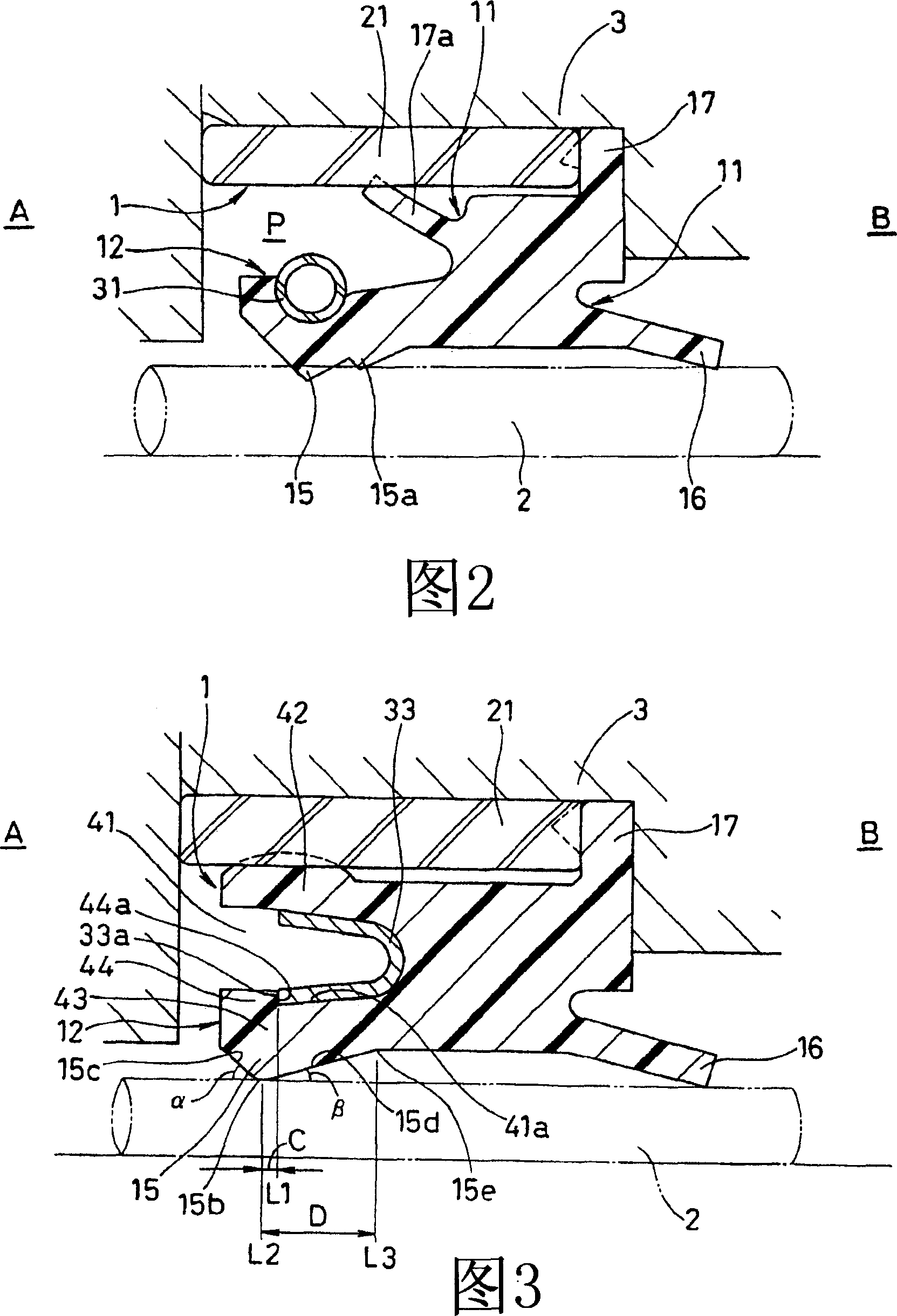
Fig. 2 is a sectional view of key parts of a pump piston seal 1 according to a second embodiment of the present invention.

[0032] In the pump piston seal 1 shown in FIG. 2 , unlike the first embodiment, the seal fixing portion 17 is clamped by the end face of the housing 3 after its diameter has been enlarged and the first metal ring 21 , and has an inner circumference of the metal ring 21. side sealing lip 17a. No other ferrules are used. The fuel-side sealing lip 15 has an auxiliary lip 15a. In addition, since the seal lip 16 on the oil side has a rectangular cross-section and is reduced in diameter on the anti-seal side B, sealing performance is ensured, and therefore a coil spring is not used.

[0033] In the above structure, since the material of the sealing member 11 having the sealing lip 15 for sealing fuel and the sealing lip 16 for sealing oil is a resin material, and constitutes one sealing system integrally formed, the pressure resistance is excellent. ・Excellen...

no. 3 Embodiment

Fig. 3 is a sectional view of key parts of a pump piston seal 1 according to a third embodiment of the present invention.

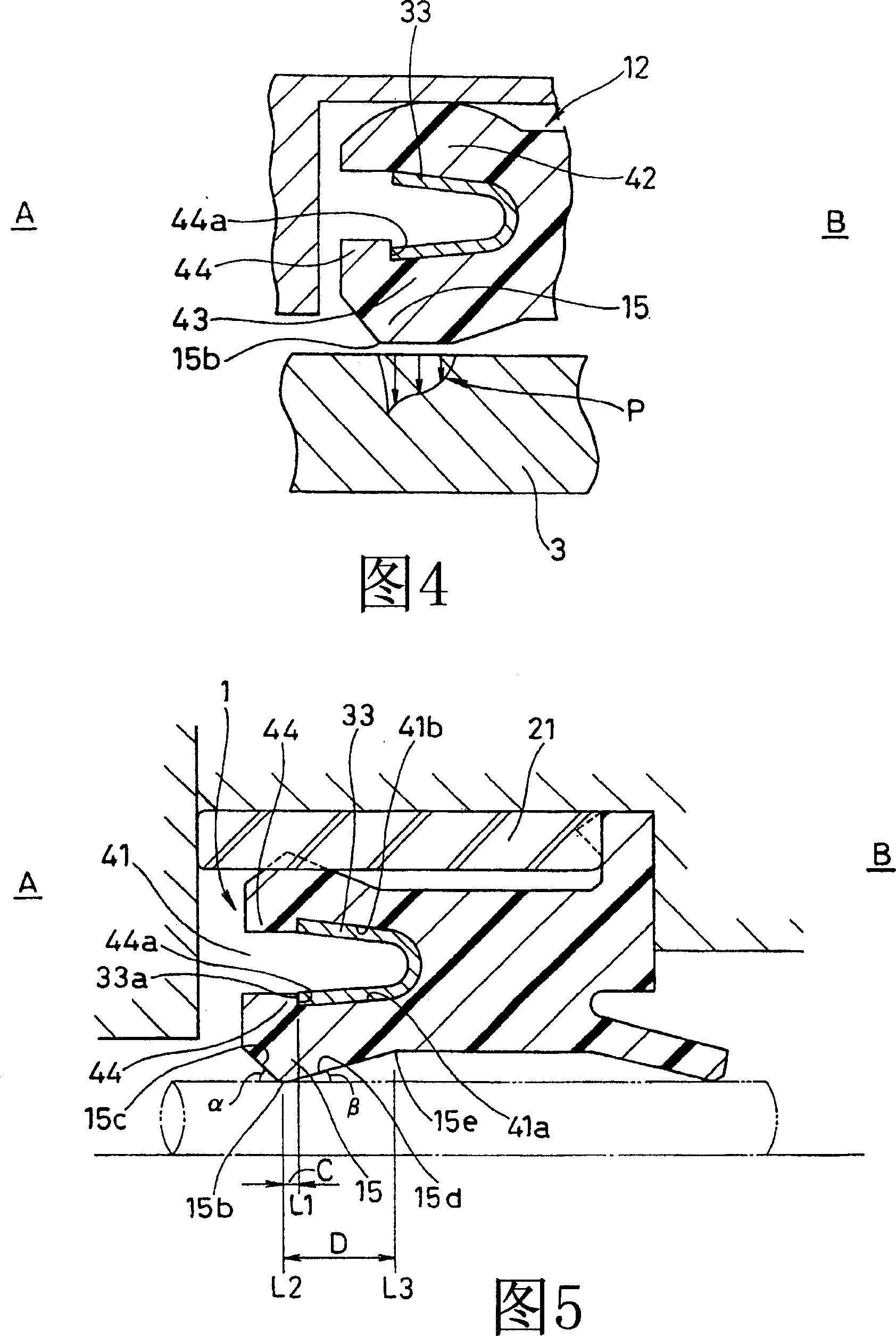
[0035] In the pump piston seal 1 of FIG. 3 , the fuel seal member 12 is different in shape from the second embodiment. That is, the fuel seal member 12 has a groove 41 opened on the side A to be sealed and has a substantially U-shaped cross section. The inner peripheral fixed sealing part 43 is formed, the metal ring 21 is fitted on the inner peripheral surface of the housing 2 , and the metal spring 33 imparting radial force is installed in the groove 41 . And no auxiliary lip 15a is provided.

[0036] The cross-sectional shape of the metal spring 33 is substantially U-shaped, and the front end surface 33a on the inner peripheral side is joined to the opening of the groove 41, that is, to the anti-sealing end surface 44a of the fixing shoulder 44 formed on the inner surface 41a on the piston side. .

[0037] The axial position L1 formed by the end surf...


PUM


Abstract

A plunger seal (1) for a pump, which is used for a fuel injection pump for a direct-injection gasoline engine, in which, even if a resin material is used as a fuel seal member (12), the plunger seal can be made compact, sealing ability is increased, and assembling man-hours can be reduced, and in which set sealing performance can be achieved when a U-shaped elastic member (33) for applying an urging force is used in a groove (41) formed in the fuel seal member (12). The resin fuel seal member (12) and an oil seal member (13) are assembled to form one seal system. Further, when the U-shaped elastic member (33) is installed in the groove (41), the axial position (L1) of an end surface (44a) that is on the side opposite the side to be sealed and belongs to a flange (44) for fixation formed on the inner peripheral surface of the groove (41) is positioned more on the side (B) opposite the side to be sealed than the axial position (L2) of a head section (15b) of a seal lip (15) of the fuel seal member (12).

Description

technical field [0001] The present invention relates to pump piston seals used in fuel injection pumps for gasoline direct injection engines as reciprocating seals for high-pressure fuel pumps and in other hydraulic, air, and hydraulic equipment. Background technique [0002] Gasoline direct-injection engines have recently injected high-pressure fuel directly into the cylinder to burn it for the purpose of meeting exhaust specifications and improving fuel costs. Therefore, fuel injection pumps for direct injection of high-pressure fuel are required to have high pressure performance. Therefore, pump piston seals used in fuel injection pumps are required to have high pressure resistance. [0003] Conventionally, as a pump piston seal used in such a fuel injection pump, there is known a rubber lip type seal member (see Patent Document 1 below) which integrally has a sealing object The fuel seal lip that seals fuel, such as gasoline, etc. under high pressure, and the oil seal l...

Claims


Application Information

Patent Timeline
IPC IPC(8): F04B53/02F02M59/44F16J15/32F04B53/14F04B53/16F16J15/12F16J15/18F16J15/3232F16J15/3284F16J15/56
CPCF16J15/3216F16J15/3276F04B53/164F04B53/143F16J15/56F02M59/442F04B53/02F02M59/44F16J15/32
Inventor 近藤洋介田边靖章石冈克敏伊东聪祐长泽晋治中山纯一冈田正敏
Owner NOK CORP
Why Eureka
Try Eureka