Undersea hydraulic coupling

a hydraulic coupling and undersea technology, applied in the direction of couplings, water supply installation, transportation and packaging, etc., can solve the problems of increasing the size and thickness of the coupling member to accommodate higher working pressure and higher subsea pressure, and the weight and size capacity of the roving to transport and install the coupling member may be limited

Inactive Publication Date: 2001-03-27
NAT COUPLING
View PDF13 Cites 50 Cited by
  • Summary
  • Abstract
  • Description
  • Claims
  • Application Information

AI Technical Summary

Problems solved by technology

However, increasing the size and thickness of the coupling member to accommodate higher working pressures and higher subs

Method used


Image

  • Undersea hydraulic coupling
  • Undersea hydraulic coupling
  • Undersea hydraulic coupling

Examples


Embodiment Construction

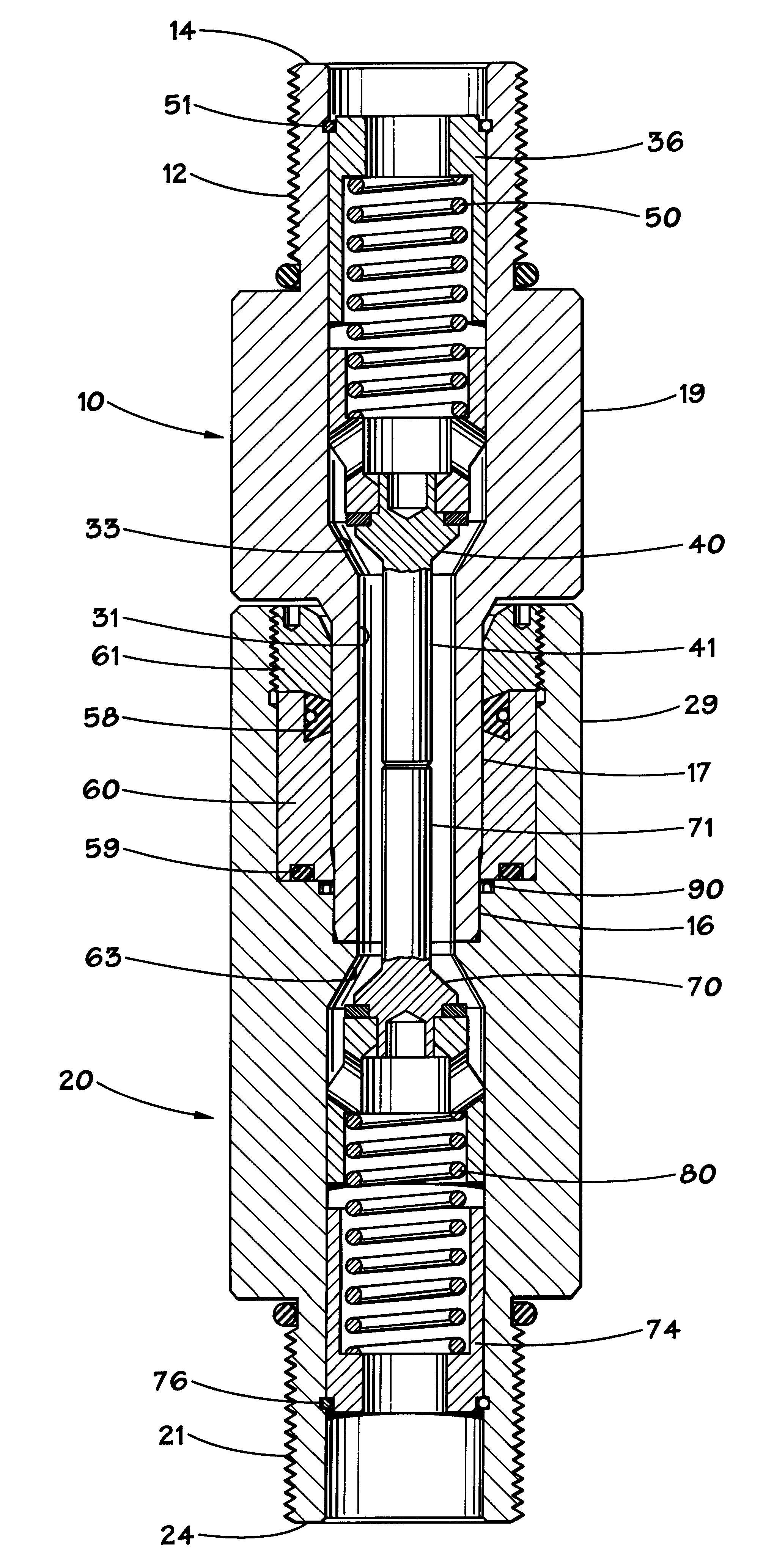
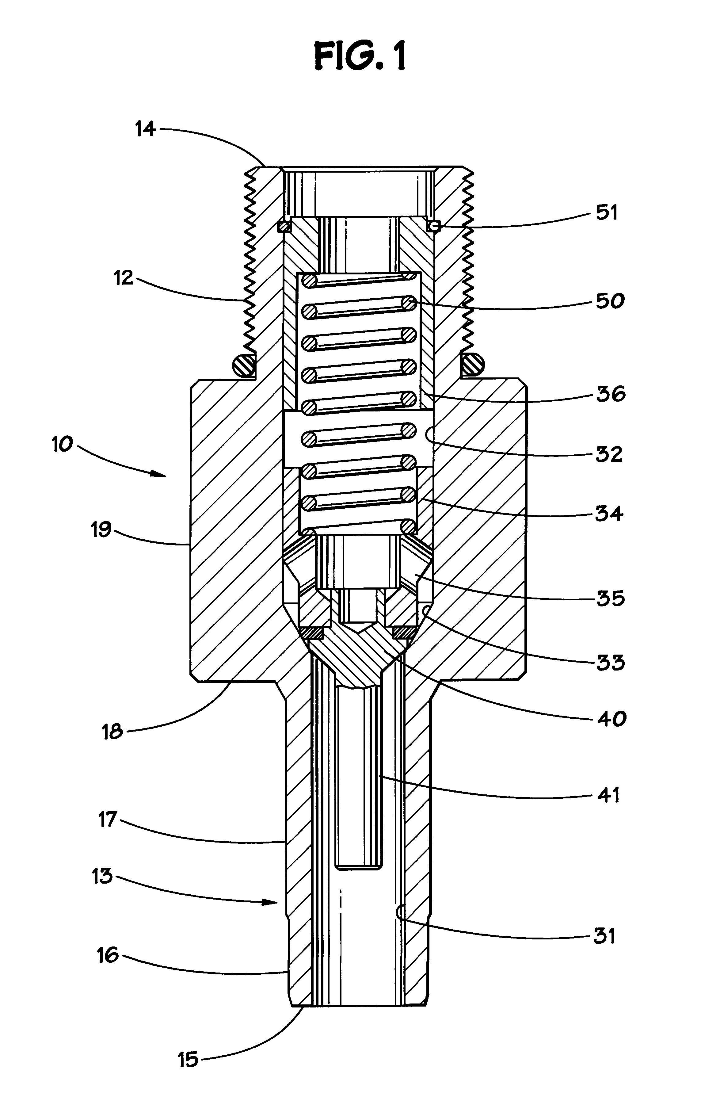
FIG. 1 is a cross-section view of a male coupling member 10 which includes a threaded handle 12 adjacent the first end of the coupling, a body section 19 which terminates at shoulder 18, and a probe section 13. The probe section 13 preferably has a stepped external diameter, with larger diameter section 17 adjacent shoulder 18, and smaller diameter 16 of the probe section terminating at the second end or leading face 15 of the male coupling member. The male member has a stepped bore with a first section 32 extending from the first end 14 to conical valve seat 33 and a smaller diameter section 31 from the conical valve seat to the second end of the male member. The poppet valve assembly of the male member is slideably received within the first larger bore 32 of the male member. The poppet valve assembly includes cylindrical, hollow valve body 34 with valve body apertures 35. Valve head 40 is conical in shape and is dimensioned to seat and seal with valve seat 33. The conical valve he...


PUM


Abstract

An undersea hydraulic coupling having a stepped internal bore dimensioned to increase the flow rate through the coupling is disclosed. The coupling allows an increased flow rate without increasing the size or weight of the coupling, by positioning the poppet valve in the body section, rather than in the probe section, of the male coupling member.

Description

1. Field of the InventionThe present invention relates generally to hydraulic couplings used in undersea drilling and production applications. More particularly, the invention involves an undersea hydraulic coupling member that is capable of holding higher pressures at increased flow rates without increasing the external dimensions or weight.2. Description of Related ArtSubsea hydraulic couplings are old in the art. The couplings generally consist of a male member and a female member, with soft seals positioned within the female member to seal the junction between the male and the female members. The female member is generally a cylindrical body with a relatively large diameter longitudinal bore at one end and a relatively small diameter longitudinal bore at the other. The small bore facilitates connections to hydraulic lines, while the large bore contains soft seals and receives the male portion of the coupling. The male member includes a cylindrical portion, or probe, at one end h...

Claims


Application Information

Patent Timeline
IPC IPC(8): F16L29/00
CPCF16L1/26F16L29/00F16L37/32Y10T137/87925Y10T137/87957
Inventor SMITH, III, ROBERT E.
Owner NAT COUPLING
Why Eureka
Try Eureka