Friction component manufacturing apparatus and method

a manufacturing apparatus and friction component technology, applied in the field of friction component manufacturing apparatus and method, can solve the problems of insufficient adhesion strength of this portion, failure to provide uniform thickness, and prone to problems in thick parts of the adhesive layer

Inactive Publication Date: 2001-04-03
NISSHINBO IND INC
View PDF0 Cites 9 Cited by
  • Summary
  • Abstract
  • Description
  • Claims
  • Application Information

AI Technical Summary

Problems solved by technology

If variations in thickness result in an excessively thin layer portion, the adhesive strength of this portion becomes insufficient.
In addition, the conventional technique fails to provide a uniform thickness, so the adhesive layer is formed to be generally thick to prevent the declines in adhesive strength associated with thin layer portions.
Thick portions of the adhesive layer are also prone to problems.
In such a portion, if the friction material becomes worn, the adhesive layer is exposed excessively early, thereby degrading elements of friction performance such as friction coefficient, wear, and fade resistance.
It is difficult, however, to provide each layer with the specified thickness when the above conventional method is used to provide a multilayer structure.
The temporary molding 10 is subsequently transferred to the next step using a conveyor, but the boss sections 10c may contact the conveyor, and it may give some damages to the boss sections.
Beyond 1.5 mm, the adhesive layer may contribute to causing friction.
Without the fibrous material, the adhesive layer will become very brittle, and in particular, the adhesive layer may be peeled off from the friction material layer, making handling difficult.
Accordingly, when an excessively large amount of fibers are present, the fibers may i...

Method used


Image

  • Friction component manufacturing apparatus and method
  • Friction component manufacturing apparatus and method
  • Friction component manufacturing apparatus and method

Examples


third embodiment

FIGS. 5 and 6 show a friction component manufacturing apparatus according to this invention wherein the friction component has a three-layer structure. According to this embodiment, a thicker portion 3c is formed in the middle of a first slide plate 3, and the void 3a is formed in this portion 3c to eliminate the need for the separate bottom plate 4. The void 3a includes a recessed portion 3d in which a boss section is formed, and the first slide plate 3 can be split into two at the center of the recessed portion 3d in both lateral directions. In addition, a second slide plate 16 is provided on the first slide plate 3, and a void 16a is formed in the second slide plate 16. The second slide plate 16 can also be moved in the horizontal direction. The void 16a constitutes a hole penetrating the second slide plate 16, and the first slide plate 3 also acting as a bottom plate for the void 16a.

A second hopper 17 is provided on the left of the second slide plate 16 and accommodates a secon...

fourth embodiment

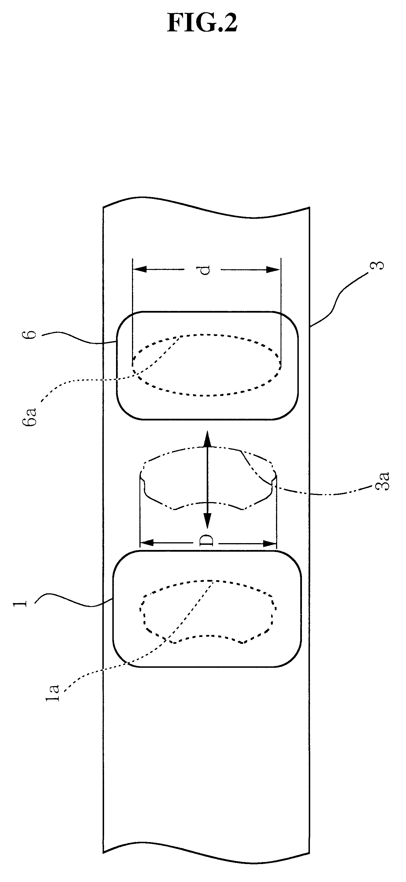
FIG. 11(a), FIG. 11(b) and FIG. 12 show this invention which is an example of a four-layer structure. FIG. 11(a) is a vertical sectional view, FIG. 11(b) is a sectional view taken along line B--B in FIG. 11(a), and FIG. 12 is a top view. According to this embodiment, a third slide plate 21 is inserted between the first and second slide plates 3 and 16. A void 21a is formed in the third slide plate 21 and consists of a hole penetrating the plate 21. In FIG. 12, the slide plates 3, 16, and 21 are moved so that the voids 3a, 16a, and 21a can be seen from above. As shown in FIG. 12, the voids 3a, 16a, and 21a all have the same size and shape as seen from above.

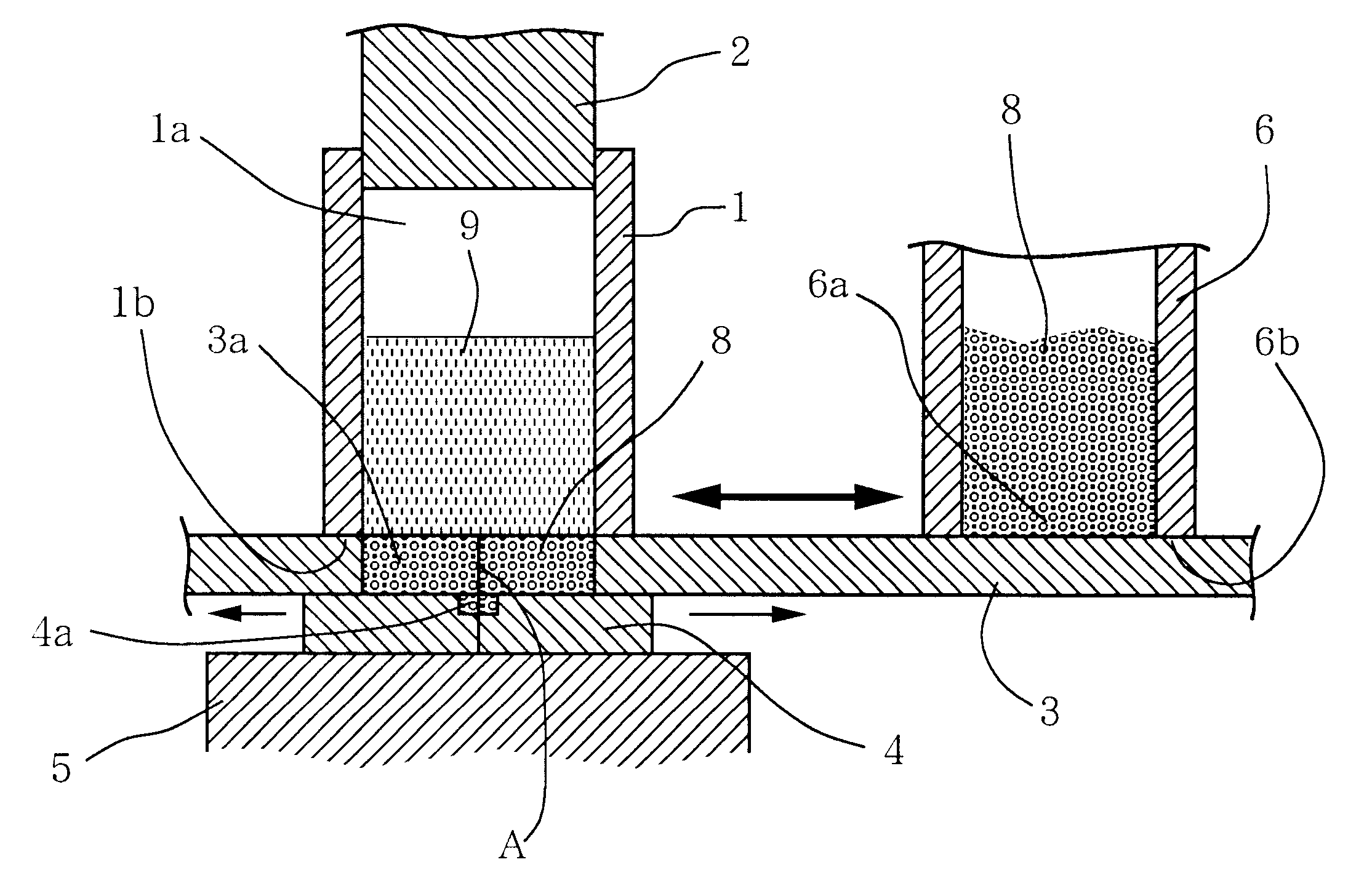
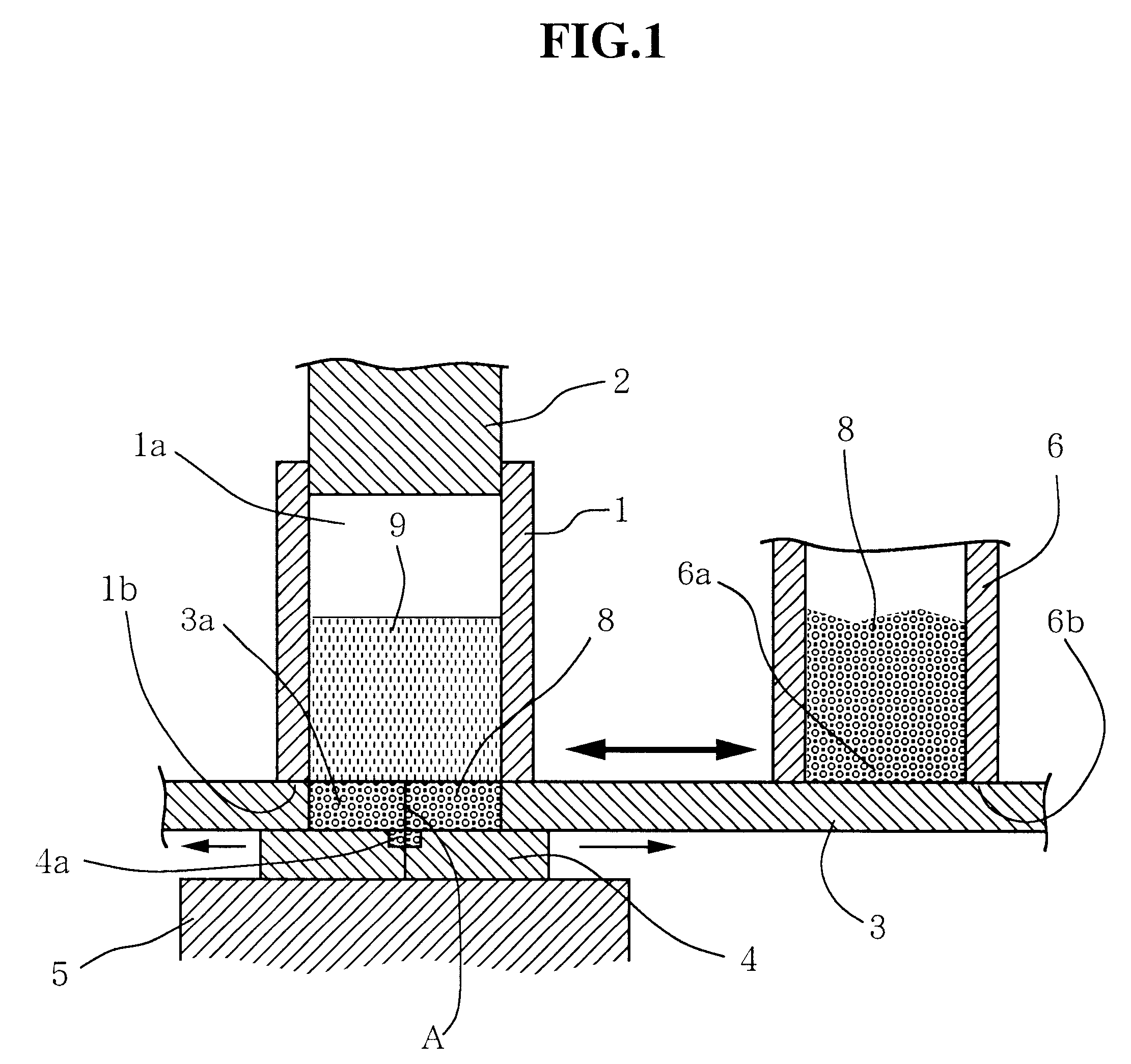
Although the first slide plate 3a has no bottom plate, it may use the bottom plate 4 as in the embodiment shown in FIG. 1. According to the embodiment in FIG. 5, the first slide plate 3 also acts as the bottom plate of the second slide plate 16, whereas this embodiment uses a separate bottom plate 22 due to the difference in heigh...


PUM

PropertyMeasurementUnit
Thicknessaaaaaaaaaa
Shapeaaaaaaaaaa

Abstract

To provide a friction component of a multilayer structure in which each layer can be formed so as to have a specified thickness, as well as its manufacturing apparatus and method.A side plate 3 having a void 3a of a specified depth formed therein is provided between a plunger 2 and a fixed mold 5 so as to move in the horizontal direction. A hopper 6 for adhesive-layer materials is provided near a molding box 1. An output port 6a in the hopper is located so as to contact slide plate 3. When the side plate 3 is moved in the lateral direction in the figure so that the void 3a is located under the hopper 6, the lower end surface 6b of the hopper acts as a leveling plate to feed an adhesive-layer material 8 into the void. The adhesive-layer material is moved to the lower part of the molding box 1, a specified amount of friction material 9 is fed in such a way that its thickness becomes uniform, and the plunger is then used to pressurize and mold the materials. By placing a plurality of slide plates one on another, a multilayer structure having three or more layers can be obtained.

Description

The present invention relates to a friction component such as a brake lining or a clutch facing, and in particular, to an apparatus and method for manufacturing a friction component in which that portion of a friction material which is attached to a back plate has a multilayer structure.DESCRIPTION OF THE RELATED ARTMany friction components such as brake linings and clutch facings constitute the products by attaching to a friction material a metal plate called a back plate, as in brake shoe assemblies, clutch disc assemblies, or disc pads; however, some products, such as brake linings, are made of friction materials alone.In addition, the friction material is formed by mixing together a fibrous material, a filler, and a binder. A powdery material comprising a mixture of these materials is placed in a molding box and pressurized and heated by a press machine to form a friction component. Two methods are used for molding: one uses a press machine to mold a temporary molding from a pow...

Claims


Application Information

Patent Timeline
IPC IPC(8): B29C31/06B29C31/04B29C43/34B29C43/20B29C43/04B29C43/36B29C43/00B29C43/14F16D69/00B29C43/18B29L31/16
CPCB29C43/006B29C43/04B29C43/146B29C43/203B29C43/34B29C43/36B29C43/361B29C31/066B29C2043/046B29C2043/185B29C2043/3615B29K2101/10B29K2105/251B29K2303/04B29K2503/04B29L2031/16B29L2031/7482
Inventor CHIBA, MASANORIKATO, TAKAYUKI
Owner NISSHINBO IND INC
Why Eureka
Try Eureka