Chaotic dynamics based apparatus and method for tracking through dropouts in symbolic dynamics digital communication signals

a symbolic dynamics and digital communication signal technology, applied in the field of symbol communication, can solve problems such as code drawbacks, performance level in bit error rate, and inability to detect in an actual communication system

US6212239B1Inactive Publication Date: 2001-04-03FRACTAL DYNAMICS
3 Cites 83 Cited by

Patent Information

Authority / Receiving Office
US · United States
Current Assignee / Owner
Publication Date
2001-04-03
Estimated Expiration
Not applicable · inactive patent

Smart Images

  • Figure 1
    Figure 1
  • Figure 2
    Figure 2
  • Figure 3
    Figure 3
Patent Text Reader

Abstract

A communication system having a transmitter chaotic signal generator and a receiver chaotic signal generator which when uncoupled generate state signals along substantially identical chaotic attractor trajectories in an out of phase relation. A controller controls the transmitter chaotic signal generator to transmit a state signal having segments of the deterministic state trajectory which identify a subsequent length of the deterministic state trajectory matching an input N-bit sequence. A receiver coupler receives the transmitted state signal and, if the signal is above a threshold for a duration of approximately two bit periods, synchronizes the receiver chaotic signal generator to the segment of its deterministic state trajectory indicated by the state signal to generate, with or without coupling, the subsequent length of that state trajectory matching the input N-bit sequence. A receiver symbol detector reconstructs the N-bit sequence based on the receiver chaotic oscillator state signal.
Need to check novelty before this filing date? Find Prior Art

Description

DESCRIPTION1. Field of the InventionThis invention generally relates to the field of symbol communication and, more particularly, to the field of symbol communication with an encoding scheme for a receiver to reconstruct symbols occurring during periods in which the received signal is too weak or corrupted by noise to be accurately detected.2. Description of the Related ArtThe ideal case in any communication system is for the receiver to detect and identify, with perfect and uninterrupted accuracy, the sequence of symbols sent out by the transmitter. However, as is well known in the prior art, this level of detection is not generally possible in an actual communication system due to, for example, channel fading and in-band noise. Conventional communication systems are therefore designed to only attain a selected performance level in terms of bit error rate. The available system architectures, design methodologies, and hardware selection criteria used by designers to achieve a workab...

Examples

first example embodiment

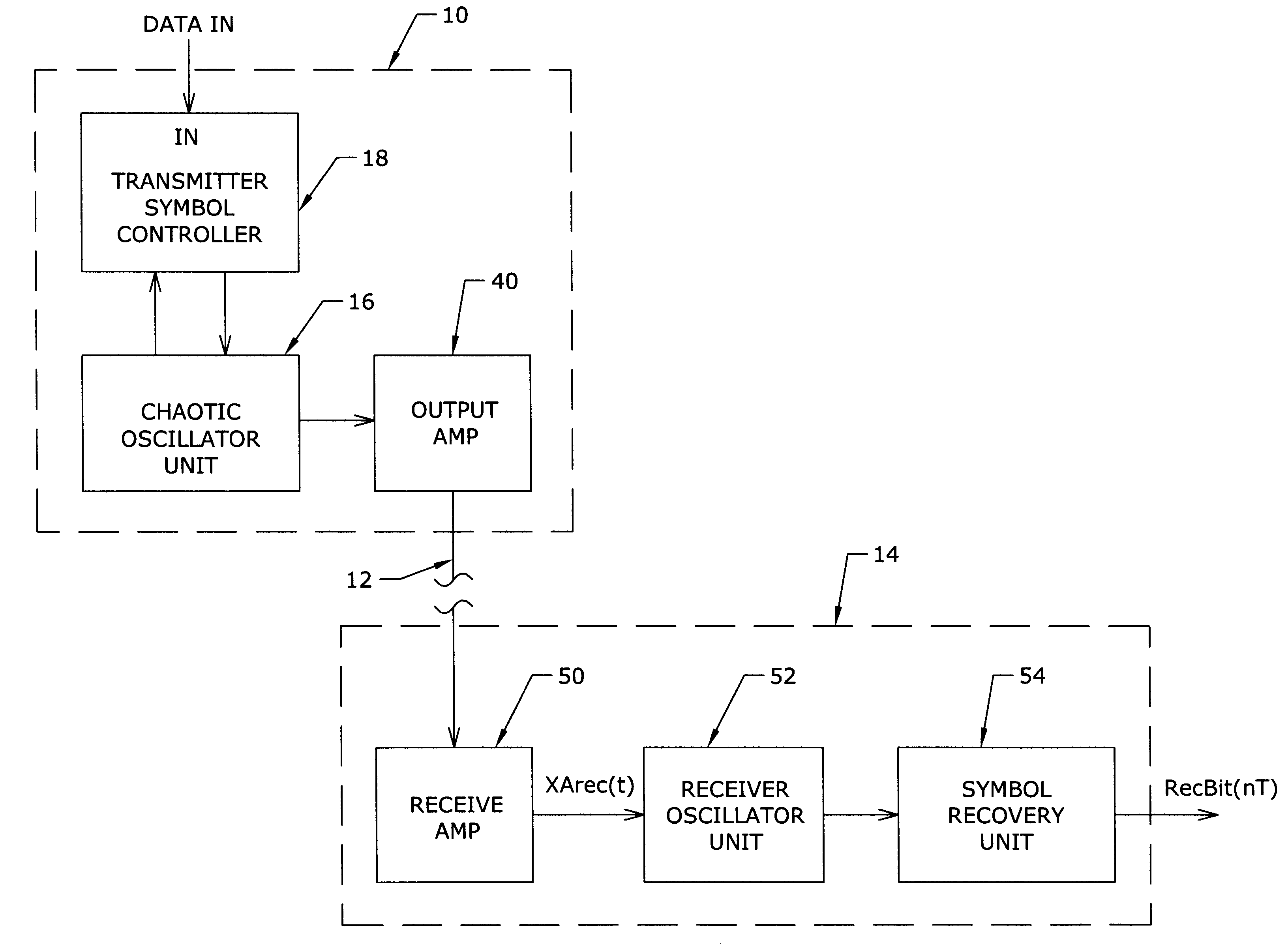
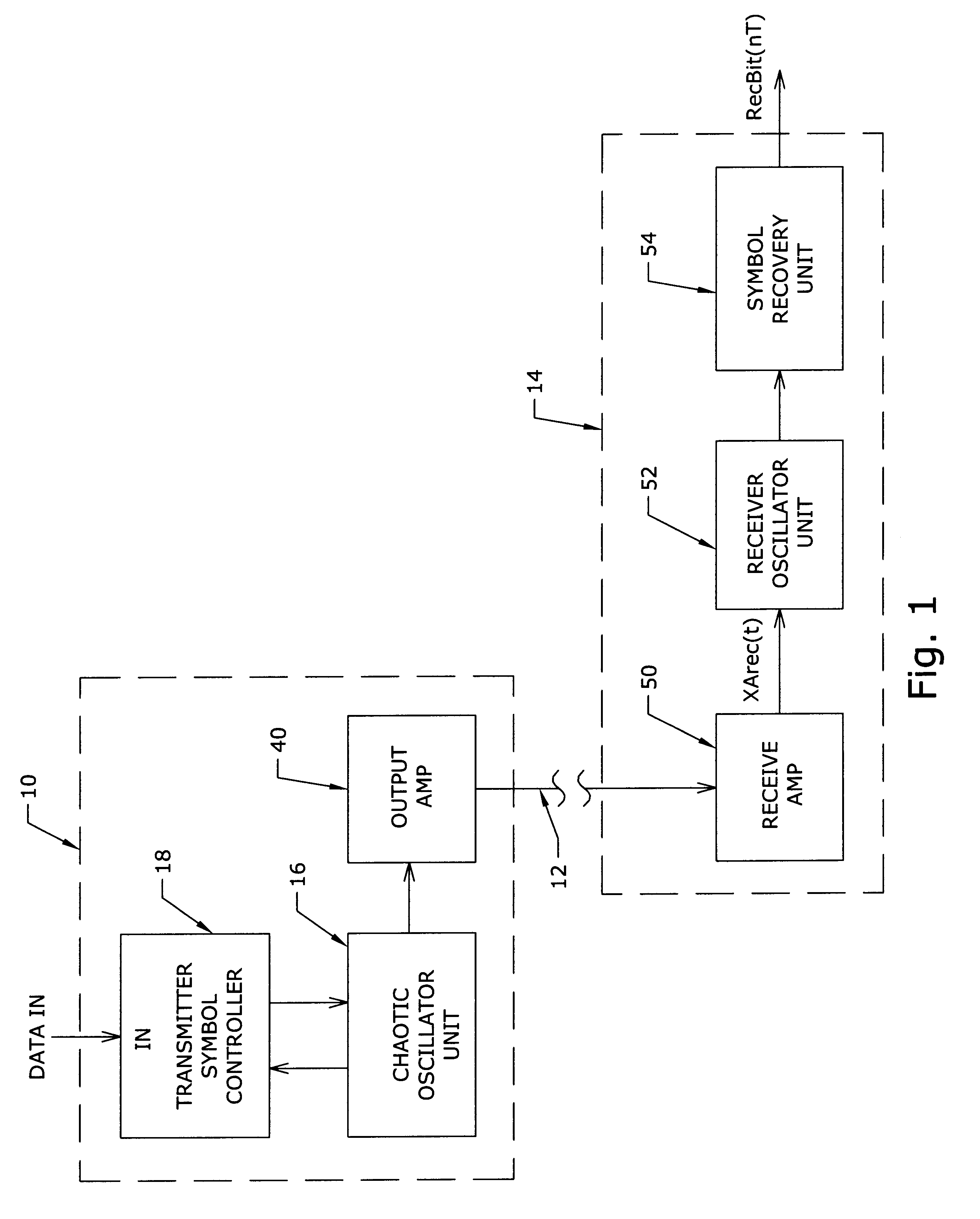
the invention will be described in reference to FIGS. 1-5. FIG. 1 is a block diagram of this example embodiment, comprising a symbol transmitter 10, a communication channel 12, and receiver / symbol reconstructor 14. The symbol transmitter 10 comprises a transmitter chaotic oscillator unit 16, a transmitter symbol controller 18, and an output amplifier 40.

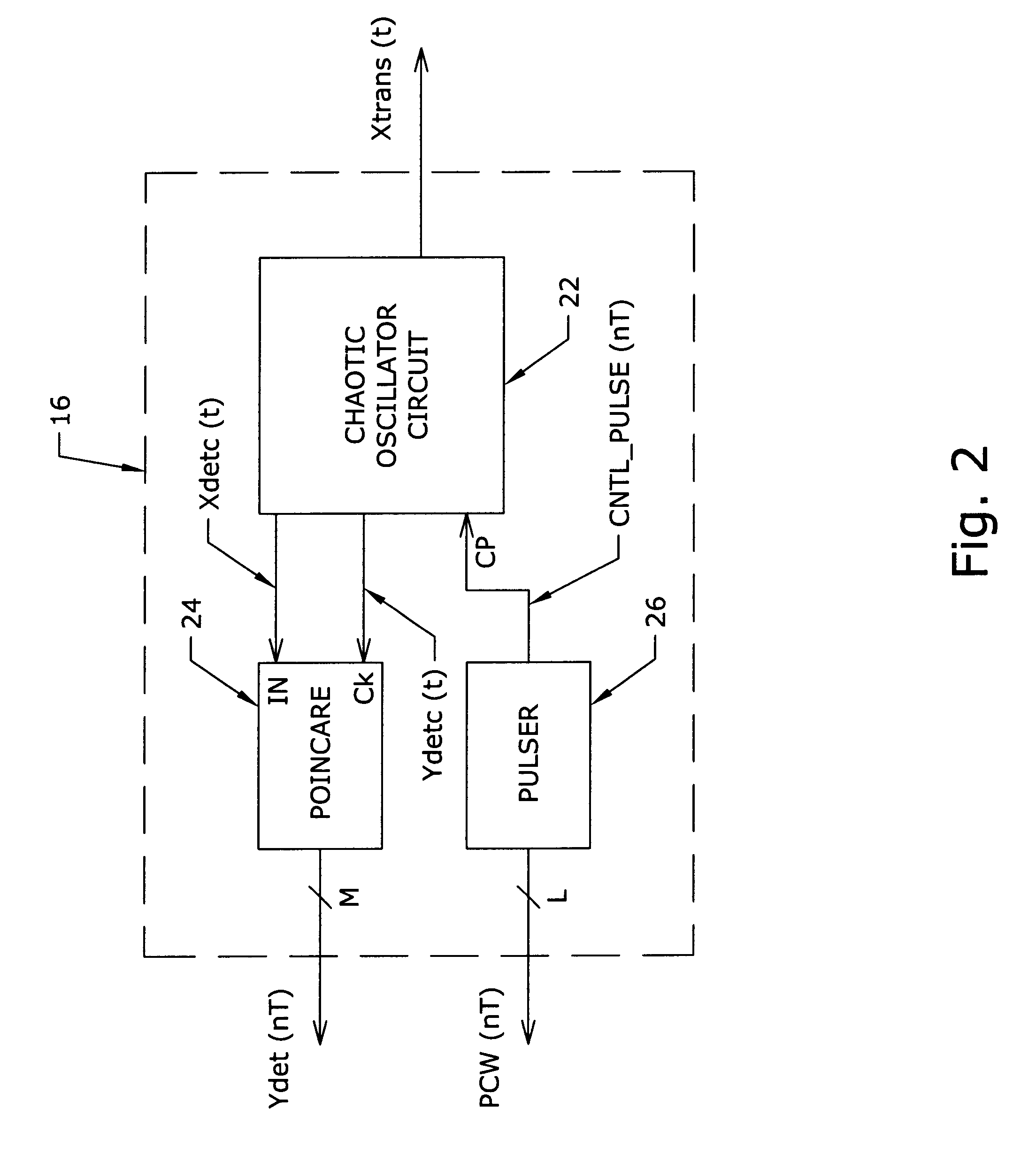
Referring to FIG. 2, the transmitter chaotic oscillator unit 16 comprises a chaotic oscillator circuit 22, a Poincare sampler 24 and a pulser 26. An example chaotic oscillator circuit 22 for this embodiment is shown by FIG. 3, and a higher level model of the same is shown by FIGS. 4 and 5. The circuit of FIG. 3 is an example Lorenz type chaotic oscillator having a free-running behavior of the form shown by FIG. 6. The axes and plots of FIG. 6 are discussed further below.

Referring to FIG. 3, the example oscillator circuit 22 is formed of four operational amplifiers OP, three diodes D, a plurality of resistors R1 through R18, a capacit...