Side-flexing conveyor belt

a conveyor belt and side flexing technology, applied in the direction of conveyors, packaging, transportation and packaging, etc., can solve the problems of adjacent belts not being placed sufficiently close together, dead-plates or other transfer means, and reinforcement elements in the form of side plates

Inactive Publication Date: 2001-04-17
AMMERAAL BELTECH MODULAR
View PDF9 Cites 53 Cited by
  • Summary
  • Abstract
  • Description
  • Claims
  • Application Information

AI Technical Summary

Problems solved by technology

However, it is a great disadvantage to have reinforcement elements in the form of side plates, steel wire or the like disposed on the outside of the chain links, in that this gives problems at the transition between the outer edge of the belt and the stationary edge on the frame which supports the conveyor.
These configurations also result in adjacent belts not being able to be placed sufficiently close together, nor can dead-plates or other transfer means be placed up against the belt's outer edge for sideways transfer of items to or from the conveyor.
This means that there are considerable limitations on how great a load can be applied to a conveyor belt, and it also places limitations on how quickly the belt can run and limitations on the length with which a conveyor can be built.
The known side-flexing conveyor belts also suffer the disadvantage that large openings can arise in the surface, so that articles such as small containers on the belt can tip over, e.g. if they are in the form of small cans or plastic bottles for soft drinks.

Method used


Image

  • Side-flexing conveyor belt
  • Side-flexing conveyor belt
  • Side-flexing conveyor belt

Examples


Embodiment Construction

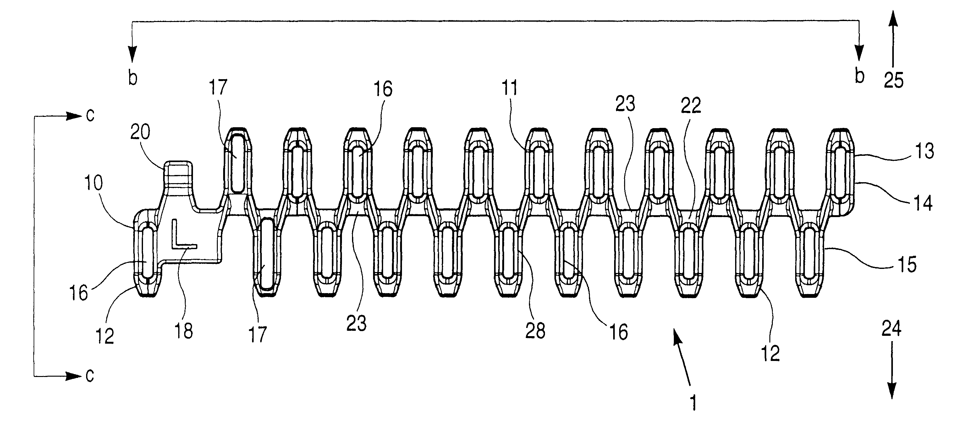
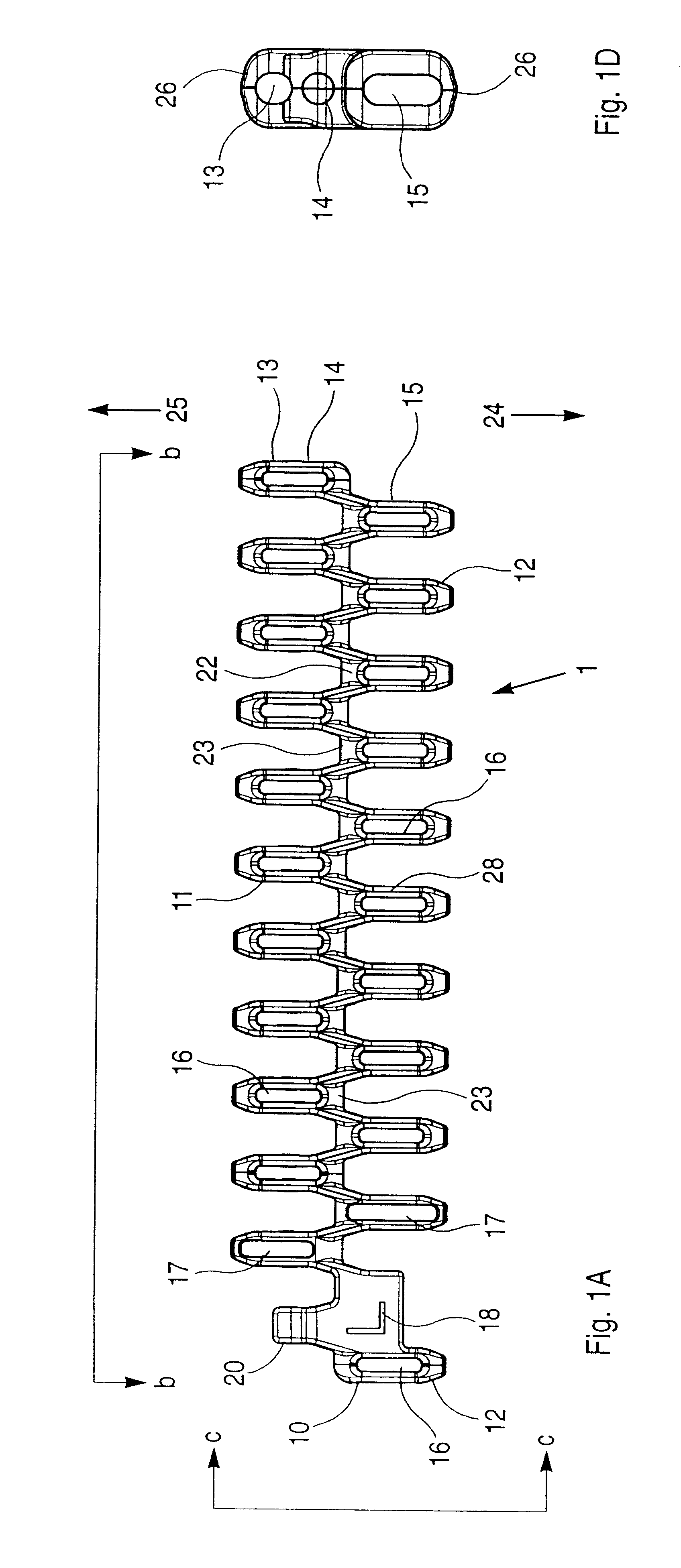
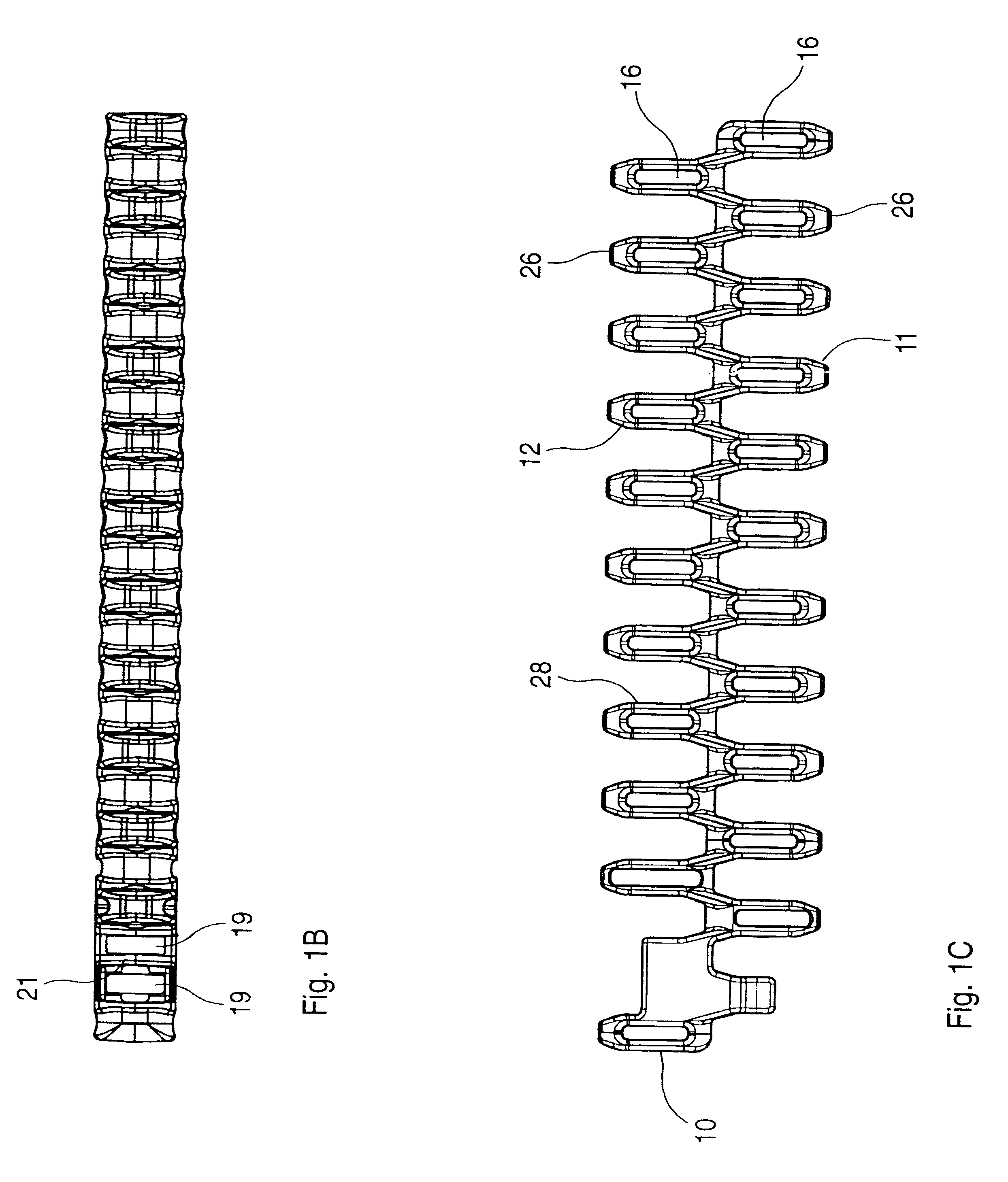
In FIG. 5 of the drawing there is shown a plane, circular section in a section in the one side of a conveyor belt according to the invention which can have an optional running direction 24 or 25. In the preceding figures, i.e. FIGS. 1-4, the edge chain links (FIGS. 1 and 2) and module chain links (FIGS. 3 and 4) which are used are shown in more detail.

The section in FIG. 5 shows that the belt is composed of edge chain links 1 and 2 and module chain links 3 and 4 with the use of transverse rods 5, 6 through openings 13, 15 in the eye parts 11, 12, see FIGS. 1 to 4.

The edge chain links 1, 2h in FIGS. 1 and 2 comprise outermost, i.e. in that side which shall constitute the edge of the conveyor belt, a reinforcement area 18, i.e. an area configured with greater material thickness to provide increased tensile strength, and a central, symmetrical bridge part 22 from which eye parts 11, 12 extend in the running directions of the belt. The eye parts in the one side are staggered in relation...


PUM


Abstract

Side-flexing conveyor belt built up of a number of chain links which are joined together in a hinge-like manner by means of transverse rods (5, 6) through openings in the individual chain links. Use is made of chain links of at least two types, i.e. edge chain links (1, 2) with one-sided reinforcement (18), and module chain links (3, 4) between the edge chain links. The chain links of both types can be configured in various module breadths, and the individual links are staggered in relation to one another. Each link has a first row of eye parts (12) with mutual intervals between them in the transverse direction, and with elongated holes in line with one another for the engagement of a transverse rod, and a second row of eye parts (11) disposed midway between the first-mentioned eye parts and with holes in line with one another for the engagement of a second transverse rod, and the two sets of eye parts are held together by a transversely-extending bridge part. The edge chain links' one-sided reinforcement (18) extends over at least one eye part for each row, so that at least one eye part is replaced by at least one traction side plate (7) in each link, in that said side plates have transverse openings corresponding to the eye part's openings and elongated holes and are in engagement with adjacent rods (5, 6).

Description

PRIOR ART TECHNIQUEThe invention concerns a side-flexing conveyor belt of the kind disclosed in the preamble to claim 1 or the preamble to claim 2.Side-flexing conveyor belts built up from a large number of chain links, substantially as disclosed in the preamble to claim 1, are known in a number of different embodiments.The individual chain links, and in many cases also the transverse rods which hold these together, are made of plastic by injection moulding or in another known manner. Plastic has many advantages which make the material suitable for this use, and therefore it is used to a great extent for straight-flow conveyor belts. If the conveyor belt is to be side-flexing, i.e. be capable of running in curves in the horizontal plane, ordinary conveyor belts of plastic and with plastic rods are of sufficient strength only if the belt is not loaded too much. This is due partly to the material and partly that the whole of the traction when the belt runs in curves is transferred alo...

Claims


Application Information

Patent Timeline
Patent Type & Authority Patents(United States)
IPC IPC(8): B65G17/30B65G17/40B65G17/08B65G17/06B65G17/38
CPCB65G17/086B65G17/385B65G17/40B65G2201/02B65G2207/12
Inventor DAMKJ.AE BUTTED.R, POUL ERIKDAMKJ.AE BUTTED.R, JOHN HAUE
Owner AMMERAAL BELTECH MODULAR
Why Eureka
Try Eureka