Low friction, direct drive conveyor belt

a conveyor belt, low friction technology, applied in the direction of gearing, transportation and packaging, hoisting equipment, etc., can solve the problems of affecting the friction coefficient of friction, affecting the tension of the belt, and the friction driven flat belt is subject to friction. , to achieve the effect of reducing friction

Active Publication Date: 2010-12-14
LAITRAM LLC
View PDF36 Cites 67 Cited by
  • Summary
  • Abstract
  • Description
  • Claims
  • Application Information

AI Technical Summary

Benefits of technology

[0016]In another aspect of the invention, means are provided to minimize friction between the belt and the drive pulley. The friction minimizing means can be a friction reducing coating the belt or the drive pulley or both. As well, the friction minimizing means can be minimal contact surfaces between the belt and the drive pulley.

Problems solved by technology

A friction driven flat belt is subject to contaminants that can affect the coefficient of friction.
Moreover, elongated belts typically stretch over time and under load and such stretching can affect its tension.
But the use of a thermoplastic toothed belt as a direct drive belt with a pulley introduces problems, primarily because of the elasticity of the belt.
Because a thermoplastic belt stretches under load, the belt teeth may not always mate with the pulley recesses or sheaves as the belt wraps around the pulley.
Yet problems remain in ensuring that the belt teeth stay engaged with the pulley sheaves over the full range of belt elongation and load in the field.
If the belt tension exceeds a predetermined maximum, the entry tooth will no longer sit properly in the pulley sheave and effective drive characteristics will be lost.
This motion causes a slight amount of vibration and noise in the system.
It may be nearly undetectable in belt applications with a small tooth pitch and a large amount of mass for damping, such as when large product loads approach a predetermined maximum for belt elongation.
But for many applications, particularly where loads are light and / or belt speed is slower, the resultant vibration and noise may be unacceptable.
Because of this necessary slip, any characteristics of a flat belt drive will compromise the benefits of direct drive, e.g. friction.
Friction between the belt and the pulley will retard slippage and may cause the trailing tooth to miss the pulley sheave altogether.
Another problem occurs when the belt is under virtually no tension.
If the belt tooth remains engaged through this arc then proper drive will be achieved, but if not, belt teeth will “pop” and the driving dynamics will become uncontrolled.

Method used


Image

  • Low friction, direct drive conveyor belt
  • Low friction, direct drive conveyor belt
  • Low friction, direct drive conveyor belt

Examples


Embodiment Construction

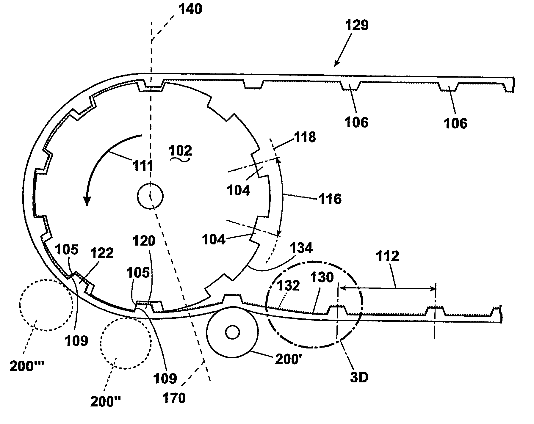
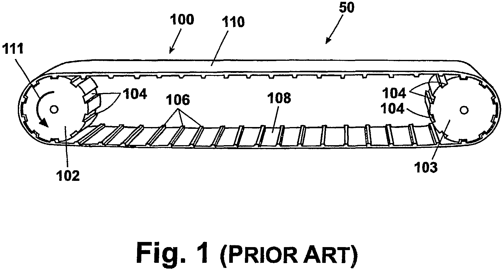
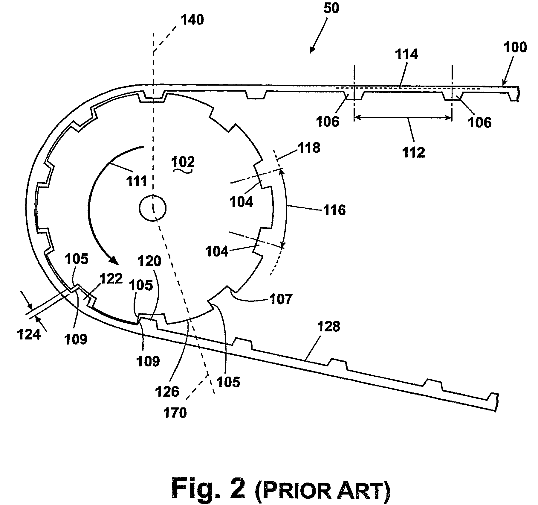
[0029]Some problems with known thermoplastic direct drive belts are shown in a direct drive conveyor 50 of FIGS. 1 and 2. An endless belt 100 is seen in FIG. 1 in a typical installation between two pulleys 102 and 103. The pulleys 102, 103 are conventional and they can be any of a number of different forms and sizes. Each pulley 102 or 103 has a number of transverse grooves or sheaves 104 spaced around its circumference. Each sheave 104 has a driving face 105 and an opposed, non-driving face 107. The belt 100 has a plurality of teeth 106 equidistantly spaced from each other on the inside surface 108 of the belt, each tooth having a driving surface 109. The teeth 106 engage the sheaves 104 of each pulley as the belt wraps around the pulley. At least one pulley, e.g. pulley 102, is a drive pulley; the other 103 can be an idler or slave pulley. In this configuration, the upper span of the belt will carry loads as the belt 100 travels in the direction of arrow 111. The belt 100 has an o...


PUM


Abstract

A thermoplastic endless belt (100) has a smooth outer surface substantially free of discontinuities and an inner surface with a plurality of teeth (106) at a given belt pitch. The teeth are adapted to engage a pulley (102) with circumferentially spaced sheaves (104) at a pulley pitch greater than the belt pitch. The belt is slightly stretchable so that the pulley can drive the endless belt when engaging the teeth within a range of load on the belt. Means (132, 136, 138) are provided to minimize friction between the belt and the drive pulley. Also, a position limiter (200) ensures that the driven tooth stays engaged optimally with the drive sheave.

Description

CROSS REFERENCE TO RELATED APPLICATIONS[0001]This application claims the benefit of U.S. application Ser. No. 60 / 593,493 filed Jan. 19, 2005BACKGROUND OF THE INVENTION[0002]1. Field of the Invention[0003]This invention relates to endless belts for conveyors and, more particularly, to thermoplastic, toothed endless belts driven by pulleys.[0004]2. Description of the Related Art[0005]Low tension, direct drive conveyor belts are often used in situations where hygiene and cleanliness are critically important. For example, in food processing plants such as those that process meat products for human consumption, low tension, direct drive belt conveyors are used to transport items. Sanitation is critically important and, therefore, the endless belts used in such conveyors are conventionally made of materials that can be hygienically cleaned.[0006]It is known to use thermoplastic belts with a smooth continuous surface on one side and teeth on the other side adapted to engage grooves or shea...

Claims


Application Information

Patent Timeline
Patent Type & Authority Patents(United States)
IPC IPC(8): F16H7/02
CPCB65G15/26B65G2201/0202F16H7/023B65G23/06F16G1/28B65G15/28B65G15/42
Inventor DEGROOT, MICHAEL
Owner LAITRAM LLC
Why Eureka
Try Eureka