Driving unit of a welding equipment

a driving unit and welding equipment technology, applied in the direction of auxillary welding devices, soldering apparatus, gearing, etc., can solve the problem of increasing the length of the pressure application sha

Inactive Publication Date: 2001-05-01
OBARA GRP
View PDF8 Cites 71 Cited by
  • Summary
  • Abstract
  • Description
  • Claims
  • Application Information

AI Technical Summary

Problems solved by technology

As a result, bearings of the pressure application shaft can not slide on the portion close to the difference in level therebetween so that a part of

Method used


Image

  • Driving unit of a welding equipment
  • Driving unit of a welding equipment
  • Driving unit of a welding equipment

Examples


first embodiment (fig.1)

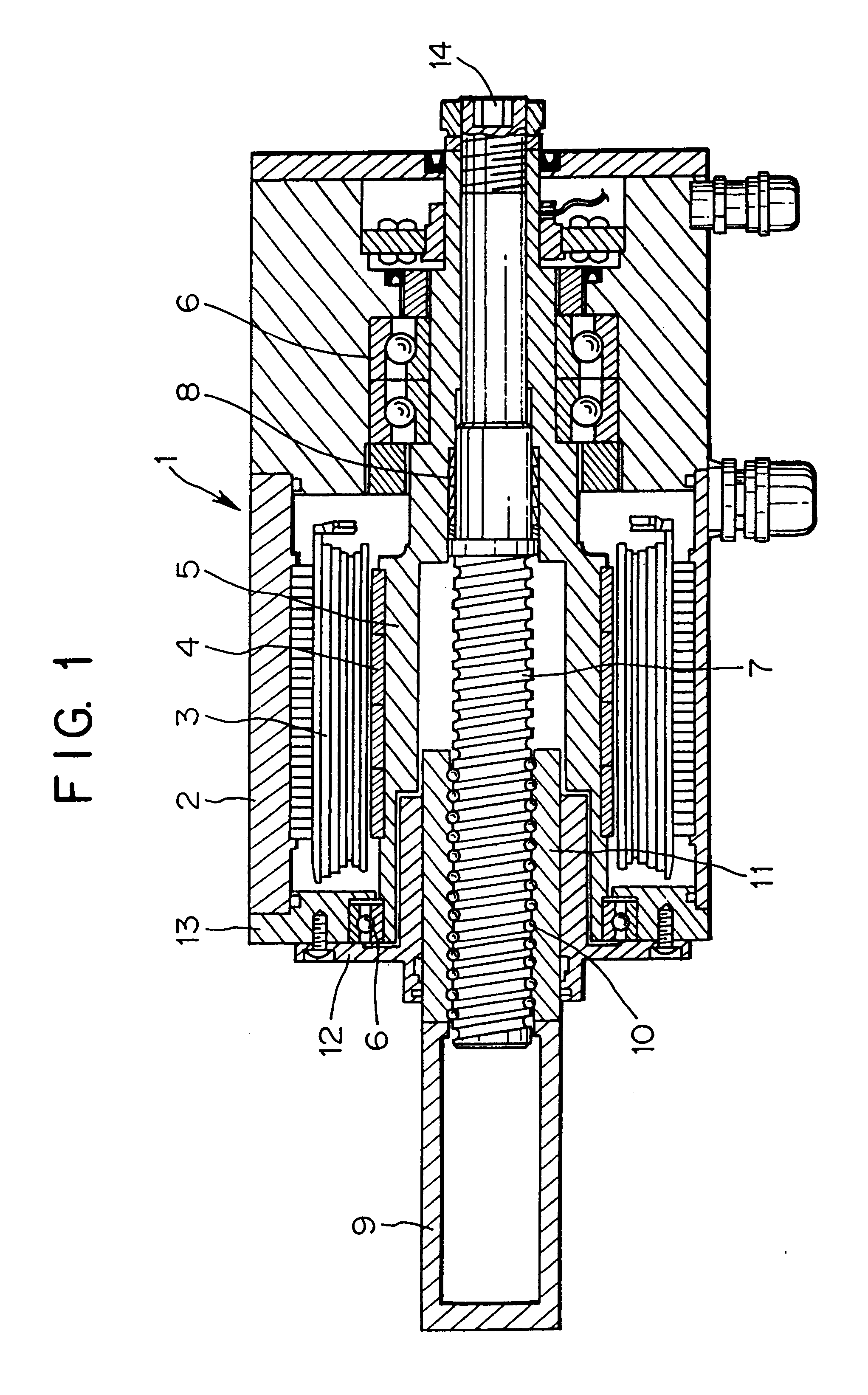
First Embodiment (FIG. 1):

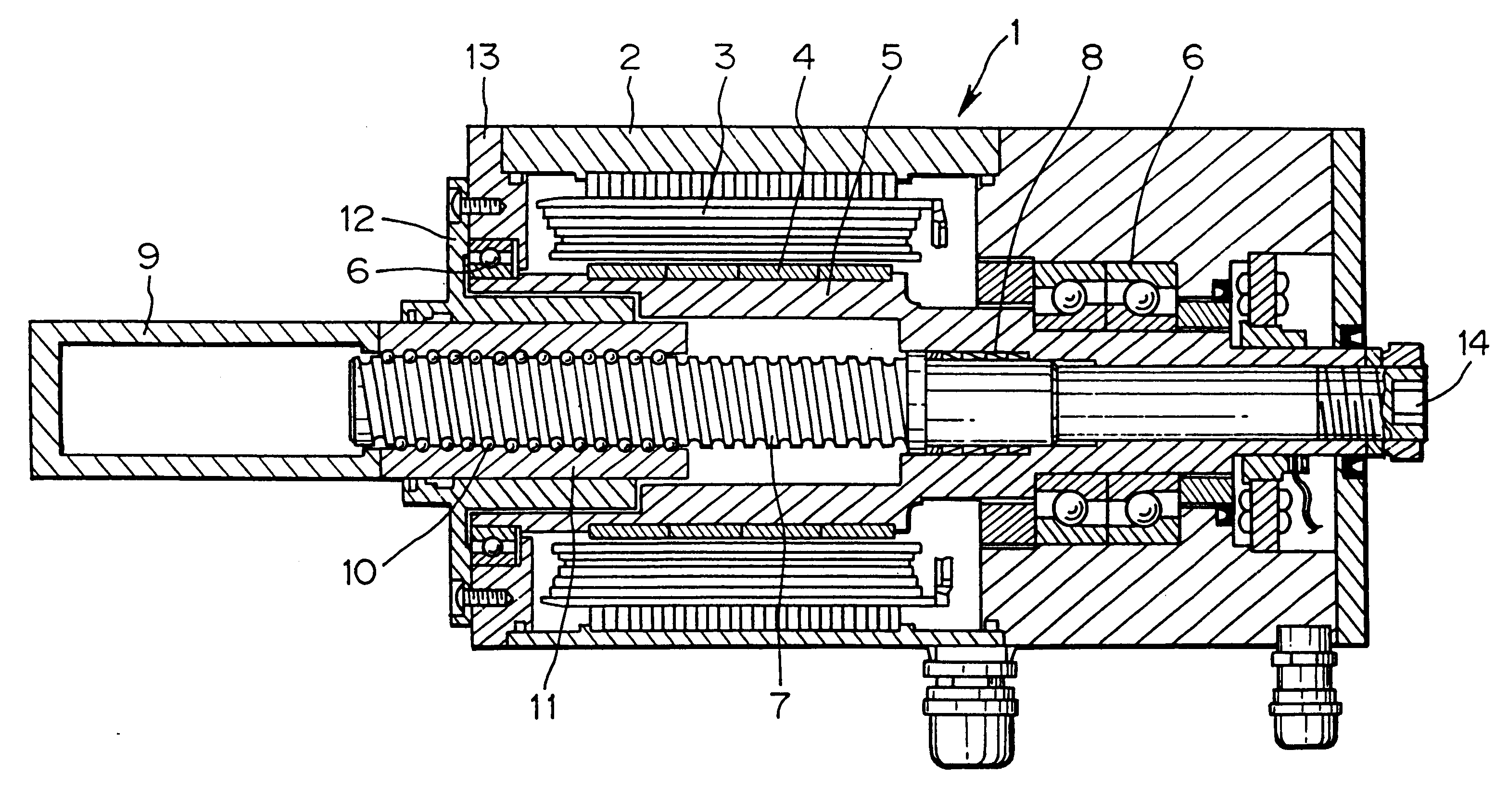
In FIG. 1, a servomotor 1 comprises a winding 3 of a stator that is fixed to an outer shell 2, a rotor magnetic pole 4 disposed at the inner periphery of the winding 3, and a rotary shaft 5 to which the rotor magnetic pole 4 is fixed, wherein the rotary shaft 5 is formed of a hollow shaft and is supported by the outer shell 2 of the servomotor 1 by way of bearings 6. A ball screw shaft 7 is positioned at a shaft core of the servomotor 1 and is fixed to the rotary shaft 5 by fixed means 8.

A ball nut 11 having a screw for indirectly engaging with a screw of the ball screw shaft 7 by way of balls 10 is fixed to a rear end of a pressure application shaft 9 by screwing or welding.

The rotary shaft 5 of the motor 1 and the ball screw shaft 7 are coaxially aligned with each other. The front part of the pressure application shaft 9 can be extended from the servomotor 1 and the tip end thereof can be connected to an electrode (not shown) for applying pressure to and ...

second embodiment (fig.2)

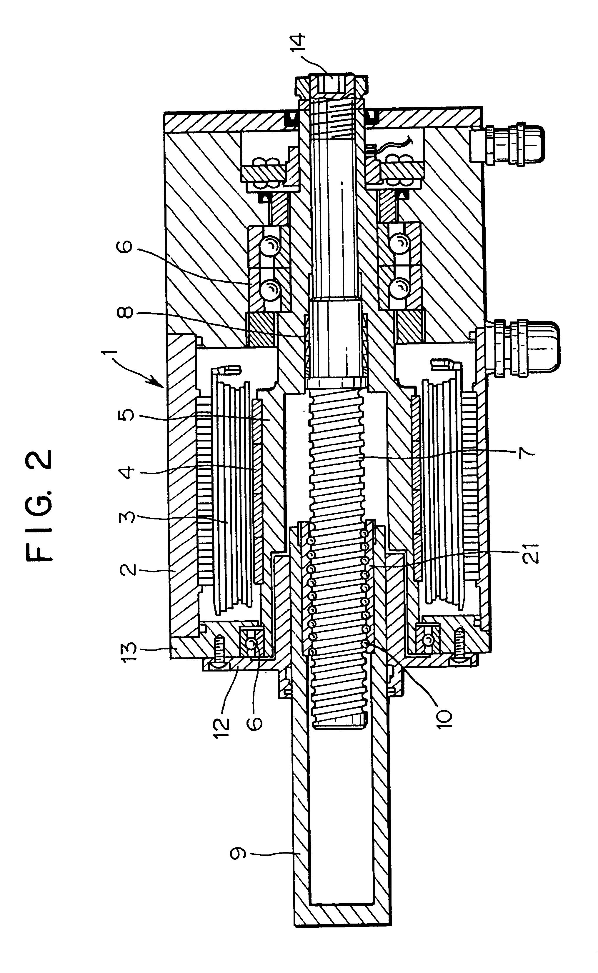
Second Embodiment (FIG. 2):

A driving unit of a welding equipment according to a second embodiment is described next. The driving unit of a welding equipment is substantially the same as that of the first embodiment except that a ball nut 21 is integrally fixed to the pressure application shaft at the inner peripheral portion of other pressure application shaft 9. Accordingly, the explanation of other components of the driving unit of a welding equipment is omitted in the second embodiment but depicted by the same reference numerals.

Although a ball screw shaft 7 is turned when a servomotor 1 turns in the second embodiment, the ball nut 21 moves along the ball screw shaft 7 as the ball screw shaft 7 is turned so that the pressure application shaft 9 integrated with the ball nut 21 is subsequently pulled inside the servomotor 1 while it moves along the inner peripheral surface of a rotary shaft 5 together with the ball nut 21 so that the amount of extension of the pressure application ...

third embodiment (fig.3)

Third Embodiment (FIG. 3):

A driving unit of a welding equipment according to a third embodiment is described next.

A rotary shaft 5 of a servomotor 1 is formed of a hollow shaft and it is supported by an outer shell 2 of the servomotor 1 by way of bearings 6. A ball screw shaft 7 positioned at the shaft core of the servomotor 1 is fixed to the rotary shaft 5 by power lock means or the like, and the ball screw shaft 7 is extended further rearward from the body of the servomotor 1 and is connected to a position detector 31.

Attached to the ball screw shaft 7 is a relatively large diameter gear 32 that forms a driven part for transmitting the torque of the servomotor 1 and is positioned between the front of the position detector 31 and the rear of the body of the servomotor 1. Positioned at the portion that is eccentric from the turning central shaft of the servomotor 1 is a relatively small diameter gear 33 that forms a manually operating driving part for applying the torque of the serv...


PUM

PropertyMeasurementUnit
Forceaaaaaaaaaa
Pressureaaaaaaaaaa
Diameteraaaaaaaaaa

Abstract

A small-sized motor is employed by a driving unit of a welding equipment wherein the inner diameter of a rotary shaft of the motor can be reduced as much as possible, and the entire length of the driving unit is reduced. The driving unit of a welding equipment is provided with a pressure application shaft. The pressure application shaft is driven by a motor including a hollow rotary shaft, a screw shaft fixed inside the rotary shaft, and a nut provided integrally with or substantially integrally with the pressure application shaft, the nut being screwed with a screw provided on the screw shaft. The rotary shaft of the motor is substantially coaxially positioned with the screw shaft. Outer diameters of the nut and pressure application shaft are respectively smaller than an inner diameter of the rotary shaft to form a direct moving guide part. The direct moving guide part is movable on an inner periphery surface of the rotary shaft and a rotary force of the rotary shaft of the motor is converted into a reciprocating motion.

Description

1. Field of the InventionThe invention relates to a driving unit of a welding equipment capable of converting a rotary output of a motor into reciprocating motion of a pressure application shaft so that the pressure application shaft can operate a gun arm or a welding jig.2. Related ArtThere is a conventional driving unit of a welding equipment, as disclosed, for example, in Japanese Patent Laid-Open Publication No. 11-197843. This driving unit of a welding equipment includes a pressure application shaft that is driven by a motor and has a portion to be pulled in the motor, a shaft of a rotor (rotary shaft) of the motor formed of a hollow shaft, a screw shaft fixed inside the rotary shaft at one end thereof, and a nut fixed to the end of the pressure application shaft and screwed with a screw provided in the screw shaft so that the pressure application shaft and the nut are movable on the inner peripheral surface of the rotary shaft.However, in the conventional driving unit of a wel...

Claims


Application Information

Patent Timeline
IPC IPC(8): B23K11/31B23K11/30F16H25/20H02K7/06B23K37/00
CPCB23K11/31B23K11/311B23K11/314B23K11/315B23K11/318F16H25/20H02K7/06F16H25/2204F16H2025/2065F16H2025/2075B23K37/00
Inventor SATO, YOSHIO
Owner OBARA GRP
Why Eureka
Try Eureka