Turbine nozzle segment band cooling

Inactive Publication Date: 2001-05-08
GENERAL ELECTRIC CO
View PDF10 Cites 108 Cited by
  • Summary
  • Abstract
  • Description
  • Claims
  • Application Information

AI Technical Summary

Problems solved by technology

Low pressure turbine nozzle bands are often not cooled, however, advanced engine designs with increased thrust to weight ratios operate at higher turbine inlet temperatures that require mo

Method used


Image

  • Turbine nozzle segment band cooling
  • Turbine nozzle segment band cooling
  • Turbine nozzle segment band cooling

Examples


Embodiment Construction

)

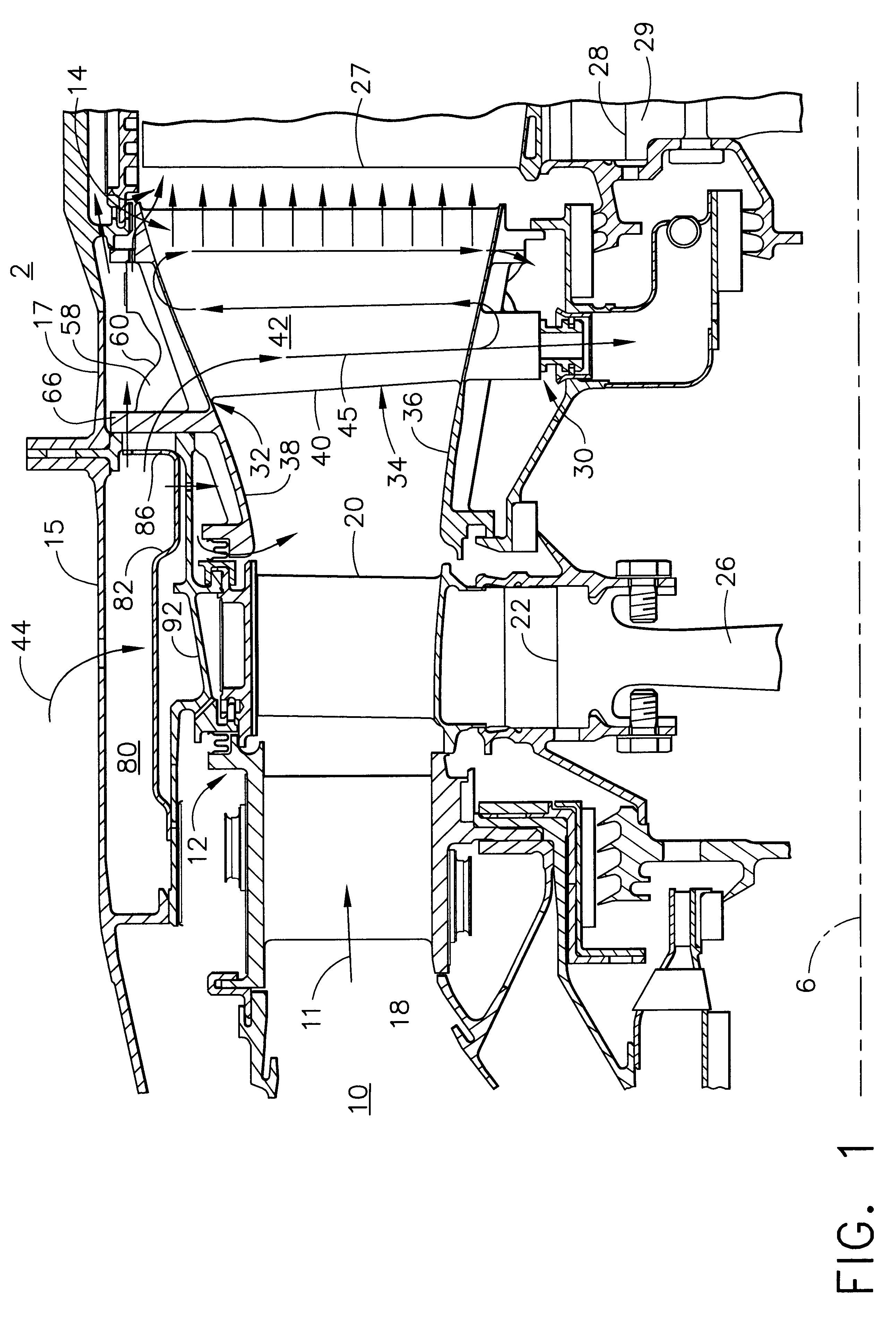
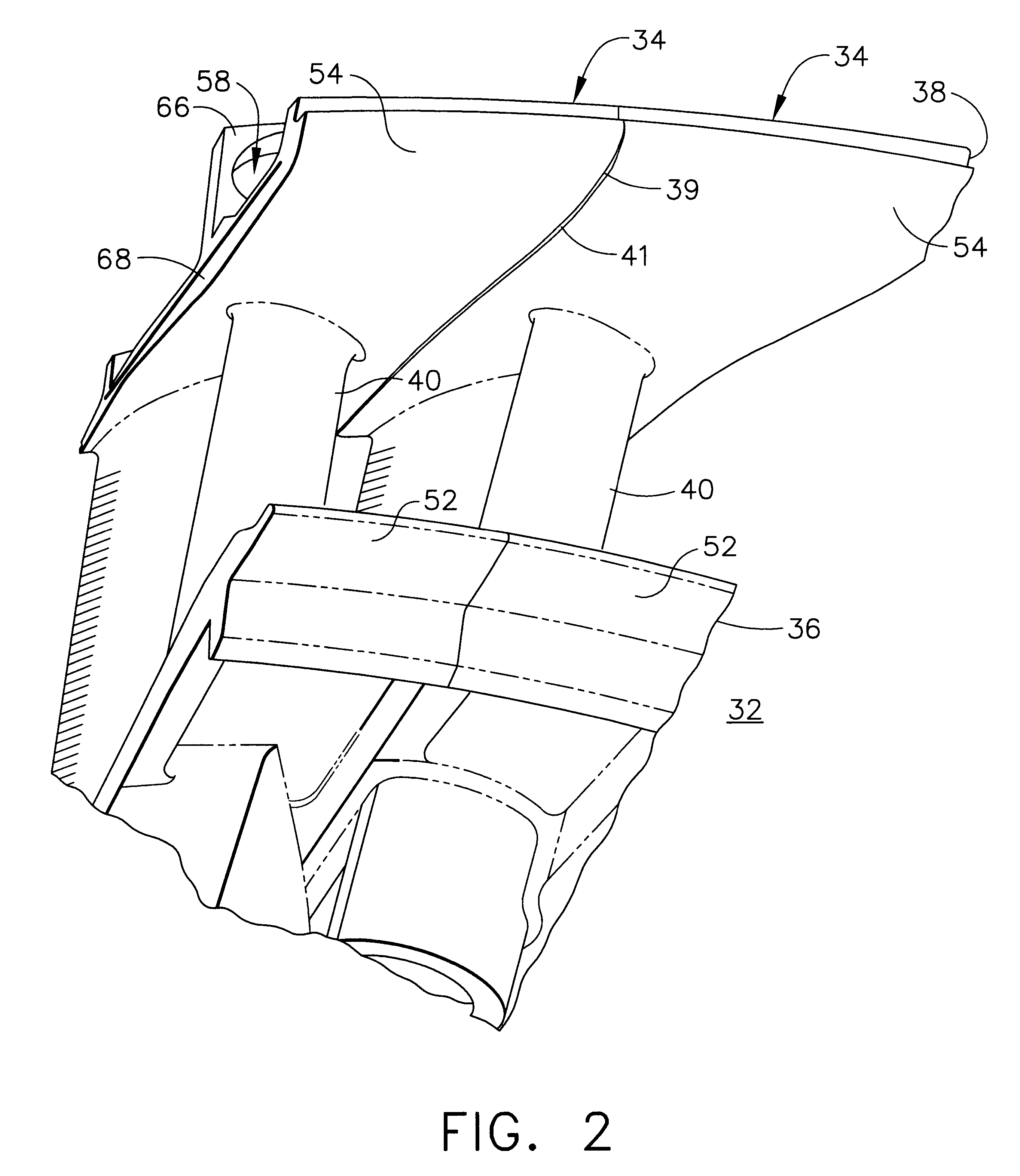
Illustrated in FIG. 1, is a portion of an aircraft gas turbine engine hot section, generally designated 2, having an axial extending centerline 6 about which runs through a combustor 10, a high pressure turbine (HPT) 12, and a first stage of a low pressure turbine (LPI) 14. Circumscribed about centerline 6 is high pressure casing 15 around the combustor 10 and the HPT 12 and a low pressure casing 17 around the LPI 14. Air is compressed in a compressor (not shown) and mixed with fuel in the combustor 10 to produce a high energy hot gas stream 11. Aft of the combustor 10 is a HPT nozzle 18 which directs the hot gas stream 11 from the combustor to HPT blades 20 mounted on a first periphery 22 around a HPT disk 26. The hot gas stream 11 is then flowed through a LPT nozzle assembly 30 having an assembly of arcuate LPT nozzle segments 32, illustrating an exemplary embodiment of the present invention, which directs the hot gas stream to LPT blades 27 mounted on a second periphery 28 aroun...


PUM


Abstract

A gas turbine engine nozzle segment includes at least two circumferentially adjacent vanes joined together along an interface between the vanes. Each of the vanes includes a hollow airfoil disposed between radially inner and outer band panels and a cooling air intake duct leading to a hollow interior of the airfoil for directing cooling air into the hollow interior. The intake duct has a duct wall protruding radially outward from the outer band panel and at least one impingement cooling hole disposed through the intake duct wall and circumferentially and radially inwardly angled. A flange portion extends circumferentially along the outer band panel and an opening in the flange portion is in fluid communication with the intake duct. The hollow airfoil, radially inner and outer band panels, intake duct wall, and flange portion are integrally formed and, preferably, integrally cast such that the vane is a single piece integrally cast vane.

Description

1. Field of the InventionThis invention relates to aircraft gas turbine engine turbine nozzle segments and, more particularly, to cooling of bands between which airfoils of the segments are mounted.2. Discussion of the Background ArtIn a typical gas turbine engine, air is compressed in a compressor and mixed with fuel and ignited in a combustor for generating hot combustion gases. The gases flow downstream through a high pressure turbine (HPT) having one or more stages including a HIT turbine nozzle and LPT rotor blades. The gases then flow to a low pressure turbine (LPT) which typically includes multi-stages with respective LPT turbine nozzles and LPI rotor blades. Each LPT turbine nozzle includes a plurality of circumferentially spaced apart stationary nozzle vanes supported between radially outer and inner bands. Each turbine rotor stage includes a plurality of circumferentially spaced apart rotor blades extending radially outwardly from a rotor disk which carries torque develope...

Claims


Application Information

Patent Timeline
IPC IPC(8): F01D25/08F01D25/12F01D9/04F01D5/18F01D9/02
CPCF01D5/18F01D9/041F01D25/12Y02T50/676F05D2230/21F05D2240/128F05D2260/201Y02T50/60
Inventor DEMERS, DANIEL E.GLEDHILL, MARK D.CURRIN, AUREEN C.TSAI, GENE C. F.
Owner GENERAL ELECTRIC CO
Why Eureka
Try Eureka