Overfill protection systems for implantable drug delivery devices

a technology for protecting systems and implantable drugs, which is applied in the field of implantable drug delivery devices, can solve the problems of severe damage to the drug administration device, overfilling or overpressurization of the device, and prior art devices presenting an obstacle to further reducing the size of the delivery device and increasing the size of the reservoir

Inactive Publication Date: 2001-05-08
MEDTRONIC INC
View PDF5 Cites 44 Cited by
  • Summary
  • Abstract
  • Description
  • Claims
  • Application Information

AI Technical Summary

Problems solved by technology

A common problem related to refilling is the potential for overfilling or over pressurization of the device.
Any additional fluid injected into the device beyond capacity of the reservoir may cause severe damage to the drug administration device and may cause other adverse consequences.
However, prior art overfill protection systems are characterized by valve displacement that is equal to the displacement of the reservoir surface and therefore require that the pump housing depth be increased to accommodate the increased valve displacement that would occur with reservoirs of increased depth.
Thus, prior art devices present an obstacle to further reduction in delivery device size and increase in reservoir size.

Method used


Image

  • Overfill protection systems for implantable drug delivery devices
  • Overfill protection systems for implantable drug delivery devices
  • Overfill protection systems for implantable drug delivery devices

Examples


Embodiment Construction

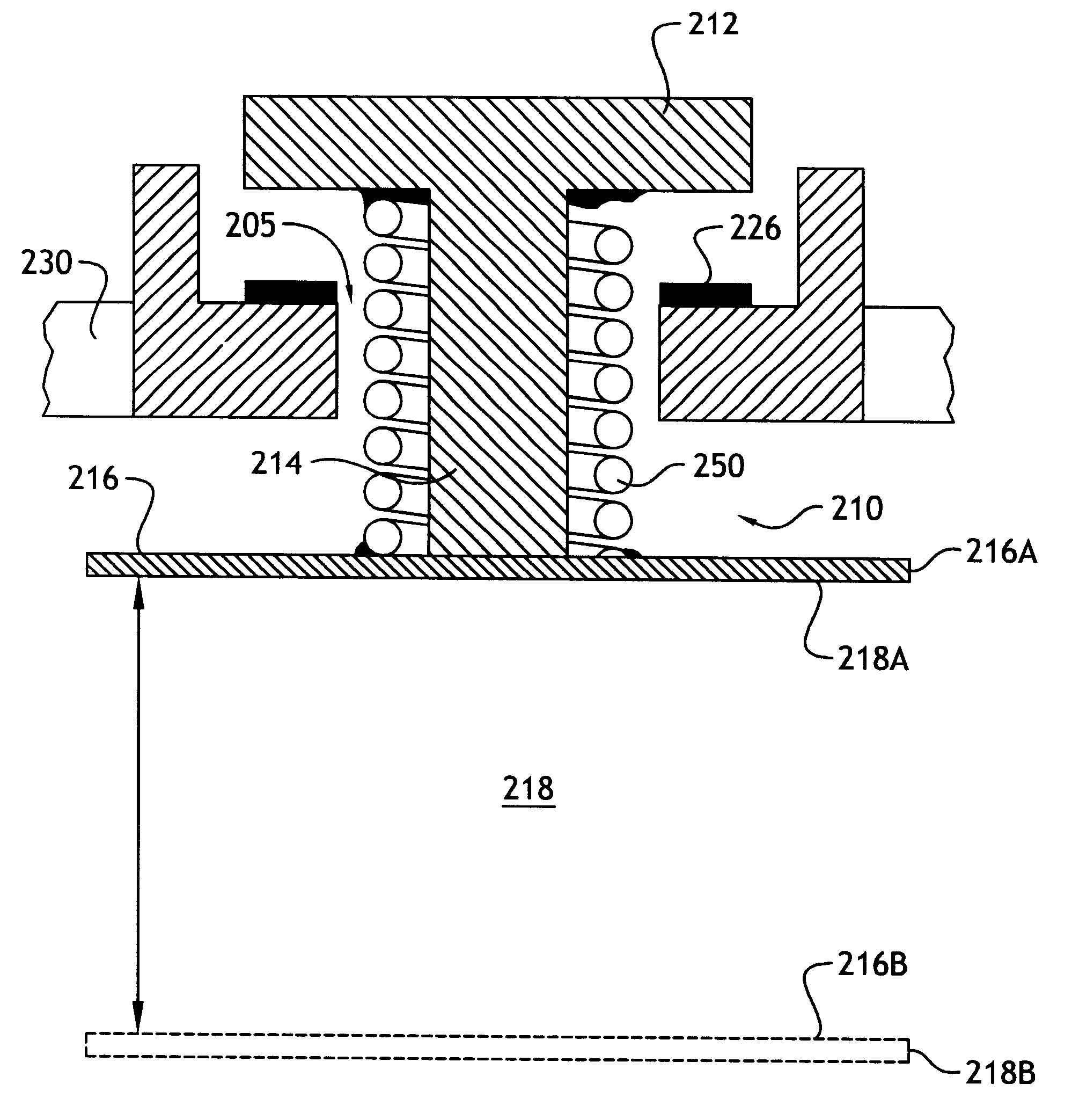
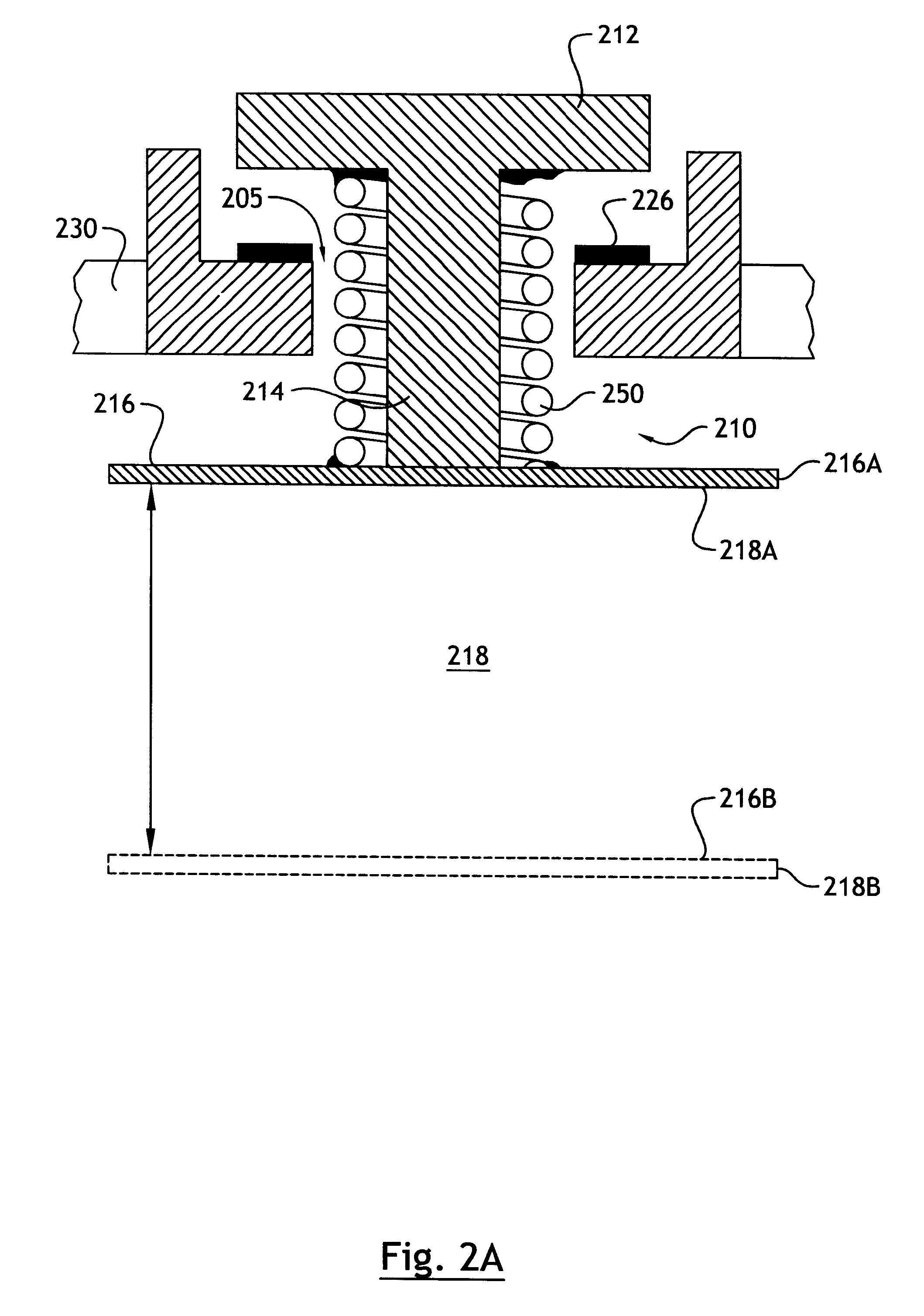
As explained in more detail below, the present invention overcomes the above-noted and other shortcomings of known systems by providing an implantable drug delivery device that incorporates a linkage system for moving a refill valve in response to movement of a surface of the reservoir, whereby the displacement of the valve is less than the displacement of the reservoir surface.

Referring to FIG. 2A, according to a preferred embodiment of the invention, a linkage system, generally referenced 210, is comprised of a collapsible link that includes a telescoping member formed by the stem 214 of valve 212 and a coil spring 250. Valve 212 is movably mounted with respect to housing 230. One end of the coil spring 250 is affixed, for example by welding or adhesive, to a surface 216 of the reservoir 218. Reservoir surface 216 is shown in a refill position 216A in which the reservoir 218 is in a collapsed position and the drug supply (not shown) contained therein is depleted. It will be unders...


PUM


Abstract

The displacement of refill valves in an implantable drug delivery device is reduced to permit the housings of a drug delivery device to remain compact in size while permitting reservoirs of increased depth to be used. In a preferred embodiment, a collapsible link is provided as a telescoping member incorporating a coil spring. As the valve is pulled into contact with its seat, a detectable pressure increase is sensed in the refill device. In accordance with the invention, as the drug supply contained in the reservoir depletes, the reservoir surface moves towards a collapsed position, compressing the coil spring and eventually contacting the valve stem, thereby lifting the valve from its seat. By virtue of telescoping link, the valve stem length and therefore the valve travel may be reduced as compared to prior art devices, thus eliminating the need for increased housing depth when deeper reservoirs are used. The collapsible link may be comprised of a second spring combined with a telescoping link. The second spring is situated on a side of the valve opposite the telescoping link, thereby providing a downward force on the valve and valve stem. As an other alternative, the invention provides a lever arm for actuating the refill valve. A pivot for the lever arm is situated near the refill valve and a distal end of the lever arm maintained in contact with the reservoir surface using a spring bias. An intermediate portion of the lever arm engages the valve stem. Thus, as the reservoir surface moves towards the collapsed position, the displacement of the valve is a fraction of the displacement of the distal end of the lever arm.

Description

Field of the InventionThe present invention relates generally to implantable drug delivery devices. More particularly, the invention relates to overfill protection systems for preventing the overfilling and over pressurization of a reservoir of an implantable drug delivery device.Description of Related ArtImplantable drug delivery systems are in widespread use to provide site-specific and / or sustained delivery of beneficial agents to address adverse patient conditions. Such delivery systems may include implantable infusion pumps, which typically include a pressurized drug reservoir and some form of fluid flow control. One example of an implantable infusion pump is the SYNCHROMED.TM. pump manufactured by Medtronic, Inc. of Minneapolis, Minn.Typically, implantable drug delivery devices are periodically refilled in situ and percutaneously using a refill device, such as a hypodermic syringe inserted into a refill chamber of the device. A common problem related to refilling is the potent...

Claims


Application Information

Patent Timeline
Patent Type & Authority Patents(United States)
IPC IPC(8): A61M5/142
CPCA61M5/14276A61M39/22A61M2209/045
Inventor OLSEN, JAMES M.ROBINSON, REGINALD D.CHRISTIANSEN, CHRISKRATOSKA, PAUL
Owner MEDTRONIC INC
Why Eureka
Try Eureka