Subscriber based smart antenna

a smart antenna and subscriber technology, applied in the direction of resonant antennas, radiating element structural forms, transmission, etc., can solve the problems of limited time domain multiple access (tdma) protocols, transmission and reception, and relatively complex techniques described in nowak

Inactive Publication Date: 2001-05-08
KRILE DAVID JAMES
View PDF7 Cites 256 Cited by
  • Summary
  • Abstract
  • Description
  • Claims
  • Application Information

AI Technical Summary

Problems solved by technology

The technique described in Nowak however is relatively complex and expensive to produce because it requires antennas having multiple polarizations.
U.S. Pat. No. 5,303,240 to Borras et al describes a similar system but it is limited to Time Domain Multiple Access (TDMA) protocols.
The system described in U.S. Pat. No. 5,430,769 to Pasiokas, et al is also similar but limited to transmission and reception of digital data because it depends on the measurement of bit transition times. Each of the described techniques is based on the premise that a more directive beam scanned over a wide angle will result in reduced mutual interference thereby improving system performance for both coverage and capacity.
However, the techniques described are not applied at subscriber units.
Despite all efforts to date, no subscriber based smart antenna system has been widely accepted primarily because of a failure to produce a cost effective device capable of supporting the large number of fixed and mobile subscribers found within a typical cellsite coverage area.
While smart antennas have been applied at base stations, their use is limited due to high cost.
Such a solution has its obvious limitations for mobile subscriber applications stemming from the fact that mobility of the subscriber unit would frequently result in the antenna beam being directed away from the base station transmitting the optimal signal.
Mounting of the antenna requires specialized labor making this a costly solution.
Furthermore, this solution is not adaptive to a growing wireless network where increased capacity requires addition of cellsites resulting in fixed subscriber antennas that are no longer directed toward the optimal base station.

Method used


Image

  • Subscriber based smart antenna
  • Subscriber based smart antenna
  • Subscriber based smart antenna

Examples


Embodiment Construction

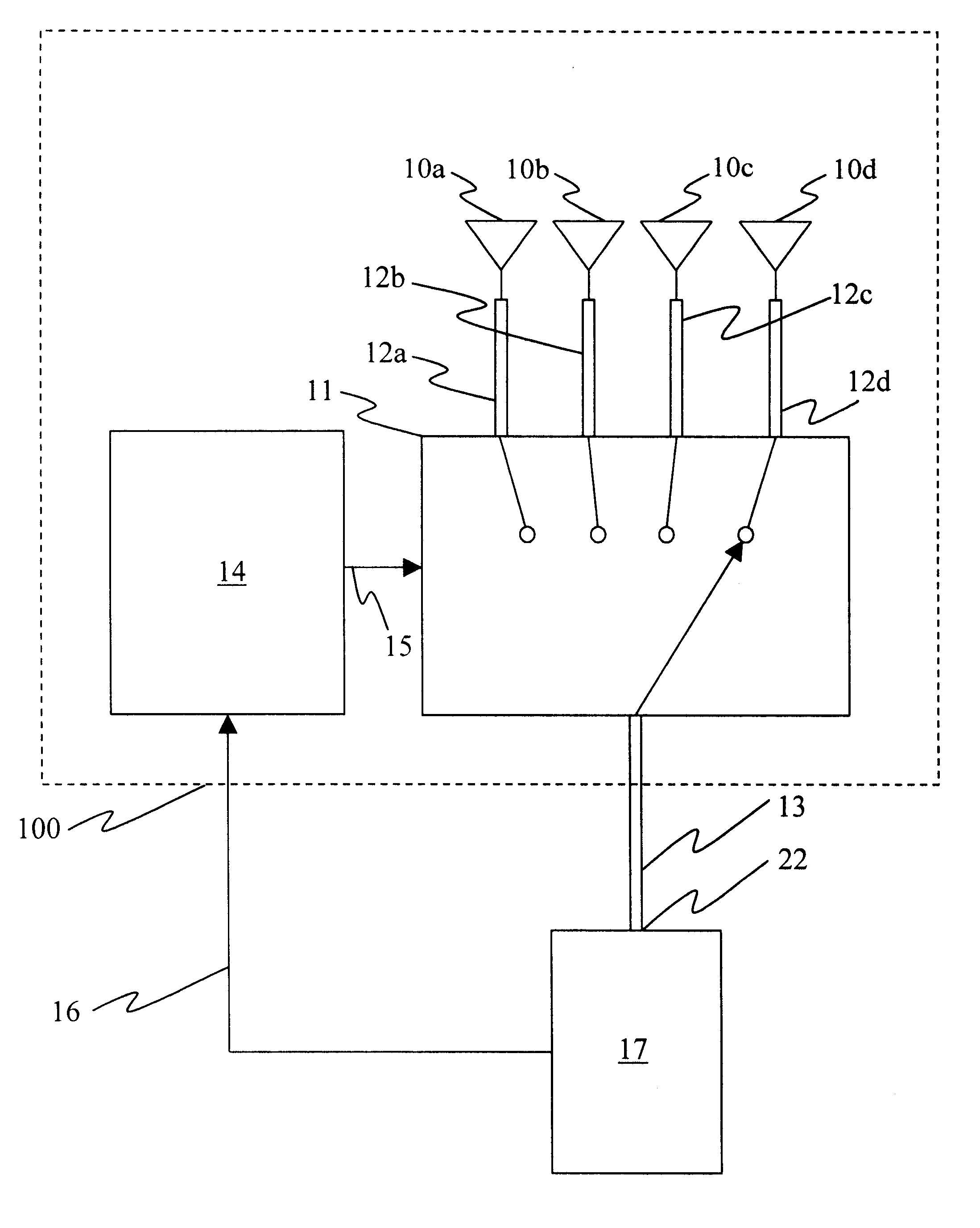
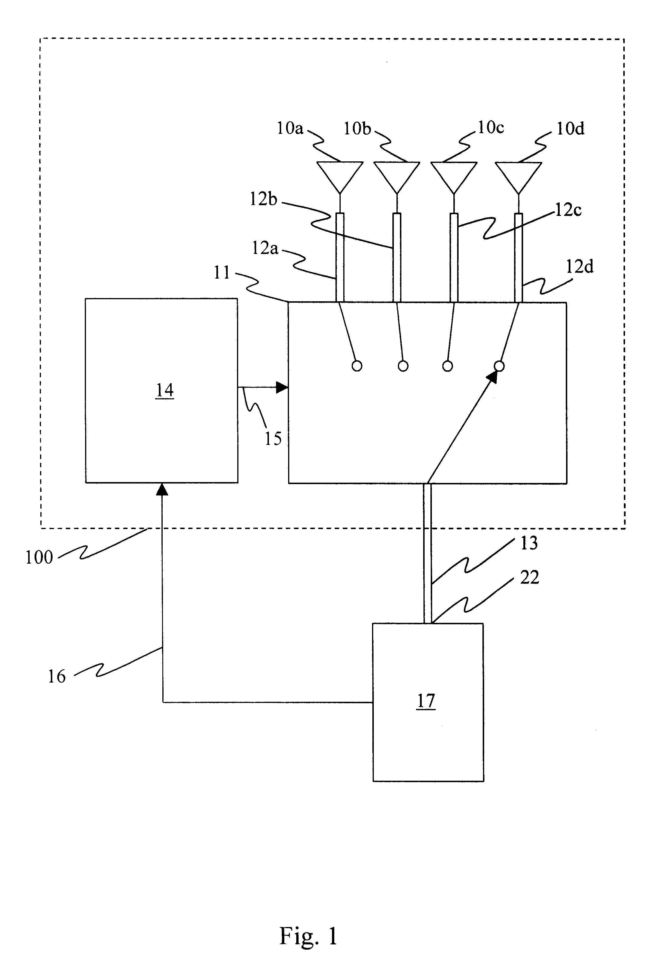
Referring to the drawings, FIG. 1 shows a block diagram of the smart antenna 100 connected to a subscriber unit 17 according to the present invention. The smart antenna consists of four antenna elements, 10a, 10b, 10c, and 10d, a radio frequency switch 11, and a controller 14. Each antenna element 10a, 10b, 10c, and 10d is connected to the selected port of the RF switch 11 through corresponding transmission lines 12a, 12b, 12c, and 12d respectively that transfer RF signals between the antenna elements 10a, 10b, 10c, and 10d and the RF switch 11. The common port of RF switch 11 is connected to subscriber unit antenna port 22 through the smart antenna transmission line 13 that transfers RF signals between the RF switch 11 and subscriber unit antenna port 22. The controller 14 is connected to RF switch 11 through a control line 15 that transfers signals from the controller 14 to the RE switch 11 and subscriber unit antenna port 22. The controller 14 is connected to the RF switch 11 thr...


PUM


Abstract

A cost effective electronically self optimizing antenna system is provided for use with each subscriber unit in both fixed and mobile wireless applications. The smart antenna consists of multiple antenna elements arranged so that individual beams independently cover sections of free space. Collectively, complete coverage of the desired free space is accomplished. The smart antenna uses a relatively narrow beam directed in the appropriate direction thereby reducing interference and improving system capacity. A controller is included which continuously monitors the signal quality and intelligently selects the optimum antenna beam pattern configuration. All telecommunication protocols, both analog and digital, can be accommodated by the controller.

Description

1. Field of the InventionThis invention relates to electronically scanned radio frequency (RF) antennas, specifically to such antennas used in fixed and mobile subscriber terminals of wireless radio frequency communication systems.2. Description of the Related ArtThe explosive growth in demand for wireless radio frequency communications necessitates increased efficiency in use of the radio frequency spectrum. In response to the problem extensive efforts have been applied to the development of antenna systems that use some form of scanning technique to improve network performance. Multiple techniques have been demonstrated such as space-diversity combining switched / multiple-beam arrays, RF scanning arrays, and digital beam forming. U.S. Pat. No. 5,903,826 to Nowak, for example, describes a wireless communication system which uses adaptive narrow beam antennas at the subscriber end of the communication link. The technique described in Nowak however is relatively complex and expensive ...

Claims


Application Information

Patent Timeline
Patent Type & Authority Patents(United States)
IPC IPC(8): H01Q3/26H01Q1/24
CPCH01Q1/246H01Q3/2605
Inventor KRILE, DAVID JAMES
Owner KRILE DAVID JAMES
Why Eureka
Try Eureka