Disarmable firing module

a firing module and disarming technology, applied in the direction of ammunition fuzes, electric fuzes, lighting and heating apparatus, etc., can solve the problems of disassembly or rework of electronics, firing modules must be destroyed using special precautions, and the firing module cannot be destroyed

Inactive Publication Date: 2001-05-15
EXCELITAS TECH +1
View PDF4 Cites 10 Cited by
  • Summary
  • Abstract
  • Description
  • Claims
  • Application Information

AI Technical Summary

Benefits of technology

Another aspect of the disarmable firing module of this invention is that it covers the combination of a firing module housing; an electronics assembly within the housing for activating a detonator; and a detonator electrically coupled to the electronics assembly when the firing module is active and removable from the electronics assembly to render the firing module inert. In this way, the firing module can be completely tested, handled, and transported in the inert condition. To activate the firing module, the detonator is inserted into the housing and electrically coupled to

Problems solved by technology

In addition, the only way to test the electronics assembly is to initiate detonation which destroys the firing module.
Moreover, to demilitarize weapon systems including prior art firing modules, the firing modules must be destroyed using special precautions due to the presence of the detonator.
Because the detonator is permane

Method used


Image

  • Disarmable firing module
  • Disarmable firing module
  • Disarmable firing module

Examples


Embodiment Construction

Other objects, features and advantages will occur to those skilled in the art from the following description of a preferred embodiment and the accompanying drawings, in which:

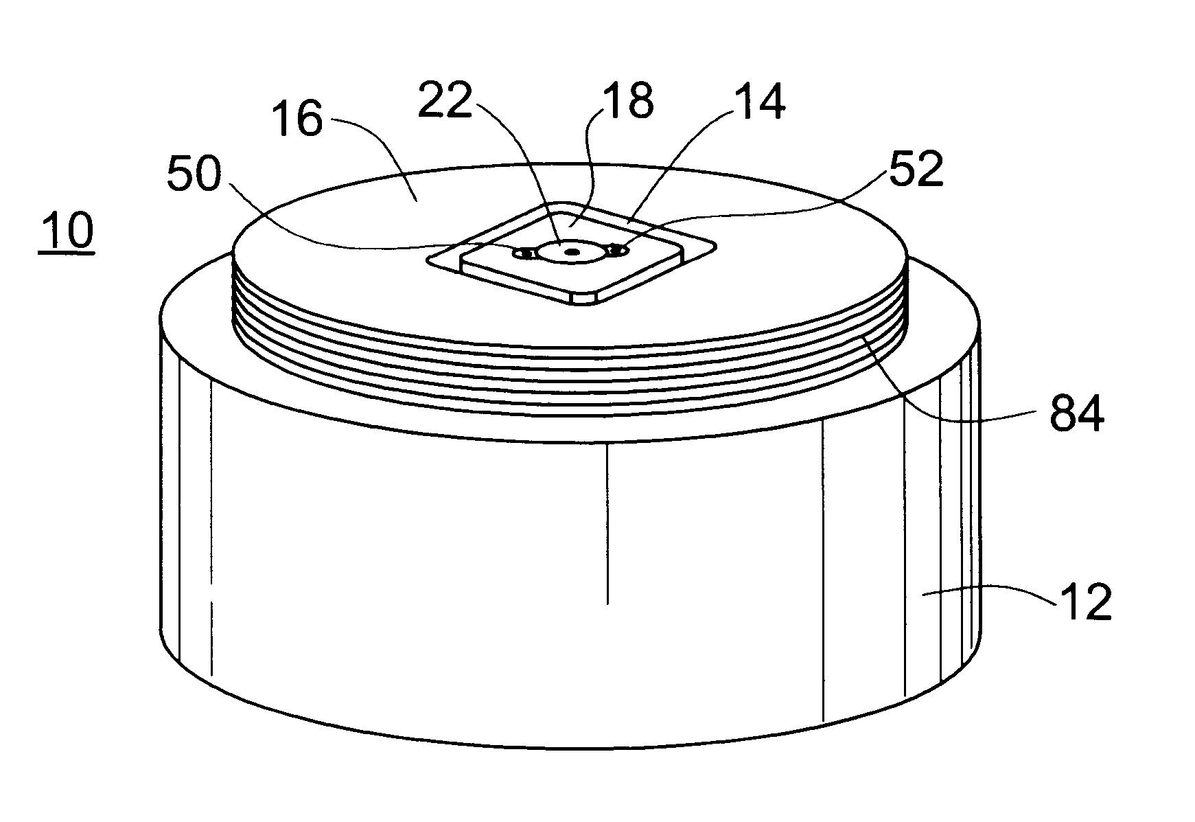
FIG. 1 is a three dimension diagrammatic view of the firing module of the subject invention;

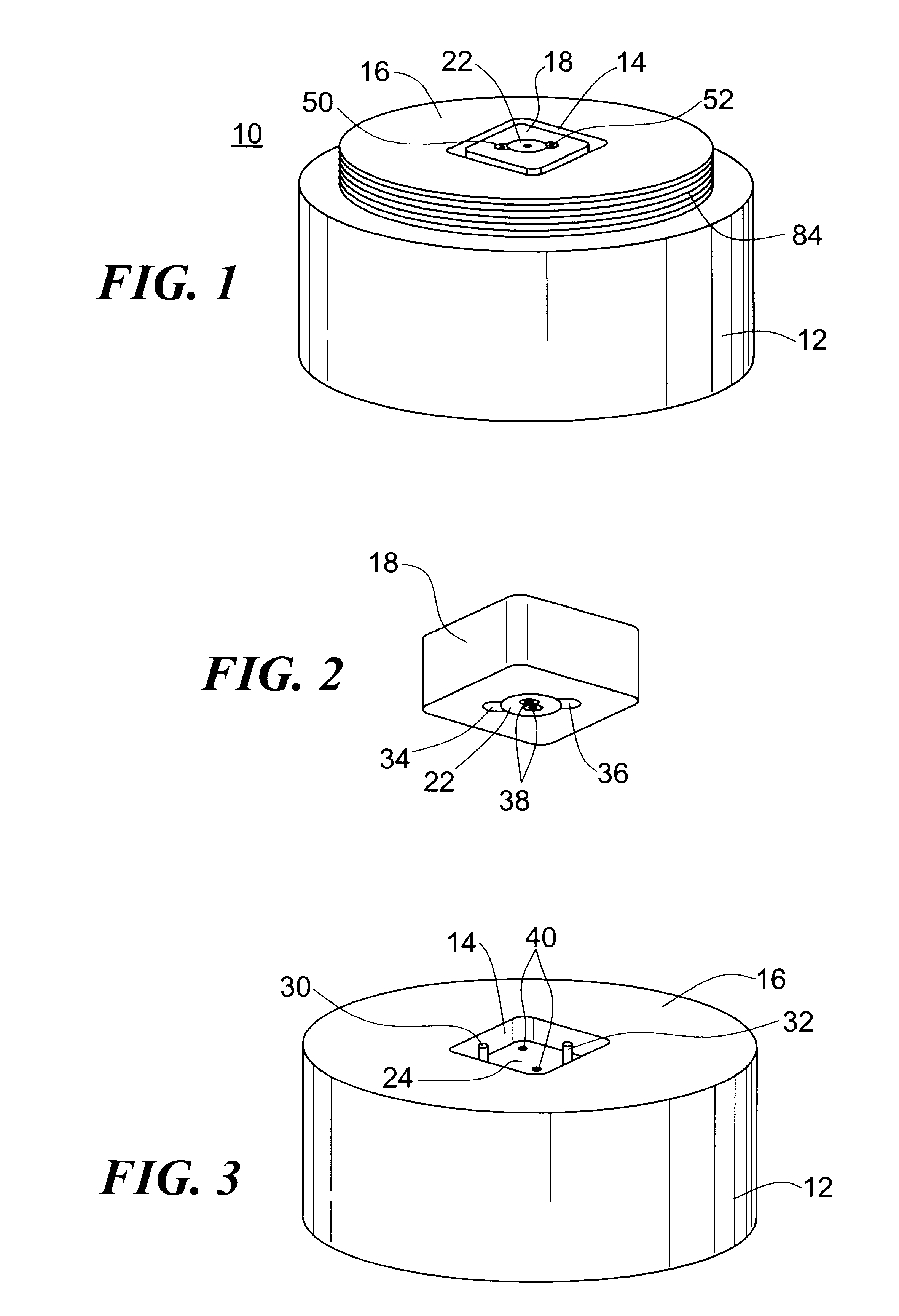
FIG. 2 is a three dimensional diagrammatic view of the detonator holder portion of the firing module shown in FIG. 1;

FIG. 3 is a three dimensional diagrammatic view of the firing module of the subject invention with the detonator removed;

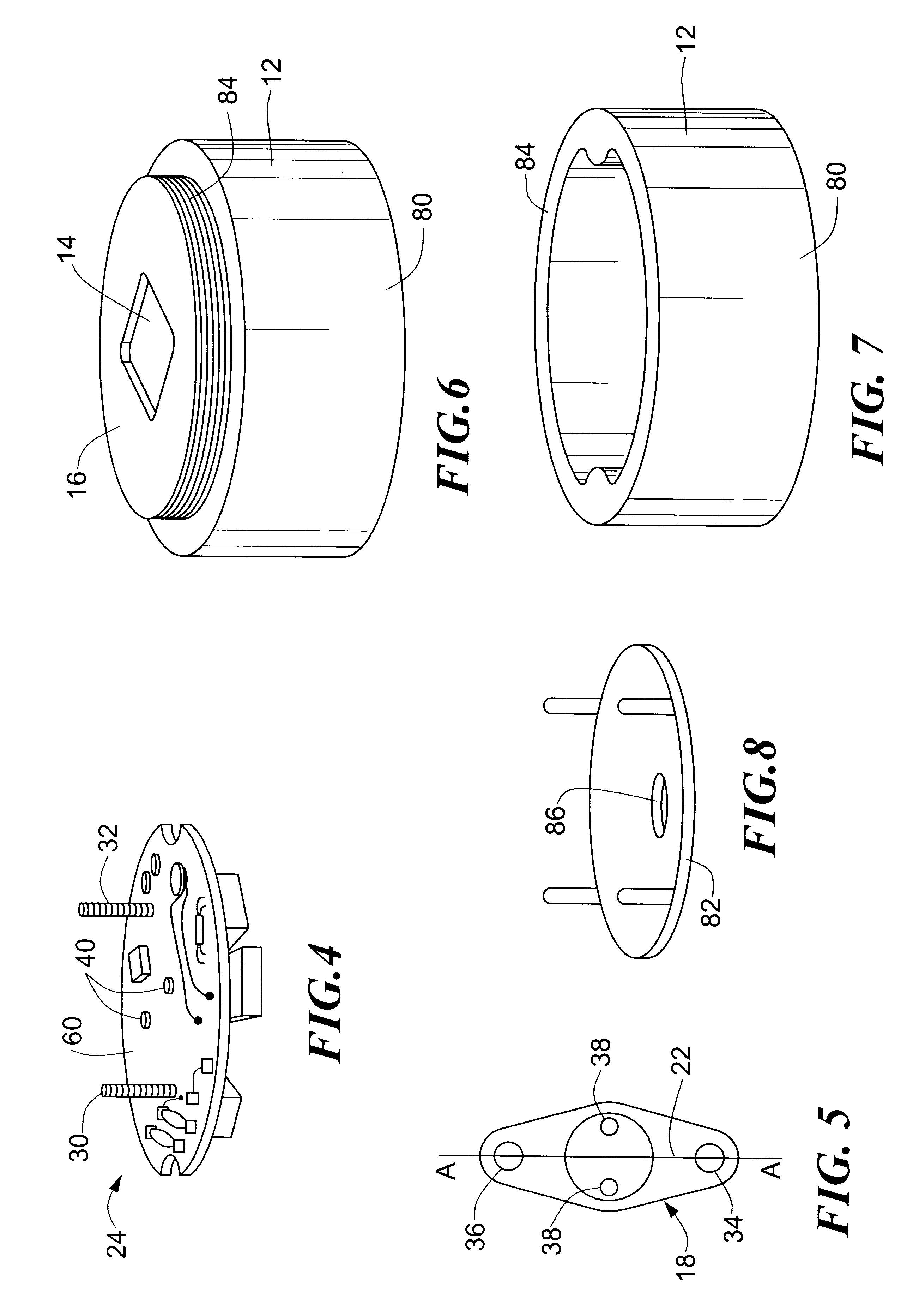
FIG. 4 is a three dimensional diagrammatic view of the electronics assembly of the firing module of the subject invention;

FIG. 5 is a bottom plan view of the detonator holder shown in FIG. 2;

FIG. 6 is a three dimensional diagrammatic view of one portion of the firing module housing of the subject invention;

FIG. 7 is a three dimensional diagrammatic view of the firing module housing shown in FIG. 6;

FIG. 8 is a three dimensional diagrammatic view of the bottom plate of the firing module ho...


PUM


Abstract

A disarmable firing module with a firing module housing having an opening therein; a detonator holder received in the firing module housing via the opening in the firing module housing, the detonator holder including a cavity therein; a detonator disposed in the cavity of the detonator holder; and a detonator electronics assembly housed within the firing module housing. The detonator holder is removably secured within the housing which allows the detonator to be separated from the detonator electronics assembly to disarm the firing module.

Description

This invention relates to firing module for detonating explosives, the firing module including a unique insertable and removable detonator which renders the firing module inert for handling, transportation, testing, and demilitarization.BACKGROUND OF INVENTIONFiring modules used in military weapon and other systems typically include an electronics assembly secured within a housing and a detonator permanently electrically connected to the electronics assembly and permanently potted within the housing. The firing module is inserted into a bulkhead containing a primary explosive and when the electronics assembly is activated it fires the detonator causing the primary explosive to explode.Firing modules of the prior art are assembled and once completed they are active due to the presence of the detonator and therefore must be handled and transported with extreme caution. In addition, the only way to test the electronics assembly is to initiate detonation which destroys the firing module...

Claims


Application Information

Patent Timeline
IPC IPC(8): F42C19/00F42B3/26F42C19/02F42B3/12F42C19/06F42B3/00
CPCF42B3/121F42B3/26F42C19/02F42C19/06
Inventor NEYER, BARRY T.ADAMS, JOHN T.DEMANA, T. ANDREWEDWARDS, JAMES C.KNICK, DANIEL R.TOMASOSKI, ROBERT J.
Owner EXCELITAS TECH
Why Eureka
Try Eureka