Heliostat for sunlight collecting system

a technology of sunlight collection and heliostat, which is applied in the direction of heat collector mounting/support, lighting and heating apparatus, instruments, etc., can solve the problems of complex and difficult control, poor performance and cost, and the project has not received good results in performance and cos

Inactive Publication Date: 2001-05-15
MITAKA KOHKI
View PDF7 Cites 37 Cited by
  • Summary
  • Abstract
  • Description
  • Claims
  • Application Information

AI Technical Summary

Problems solved by technology

Those projects, however, have not gotten good results in performance and costs.
The reason is that in order to utilize sunlight as energy, it is required to concentrate sunlight into a point to convert it into thermal energy and then to convert the thermal energy into electricity, in which there is difficulty in controlling heliostats for concentrating the sunlight into the point.
Since the above projects have attempted controlling the concave mirror of each heliostat by computer, the controlling is complex and difficult.
More specifically, the movement of the sun changes in both azimuth and altitude with time, which fact causes difficulty in controlling the concave mirrors of the heliostats in large numbers simultaneously, pursuing the movement of the sun.
As a result, the precision of information on a position sent from the concave mirror to the computer is likely to be lowered, which fact also causes difficulty in computer controlling.

Method used


Image

  • Heliostat for sunlight collecting system
  • Heliostat for sunlight collecting system
  • Heliostat for sunlight collecting system

Examples


Embodiment Construction

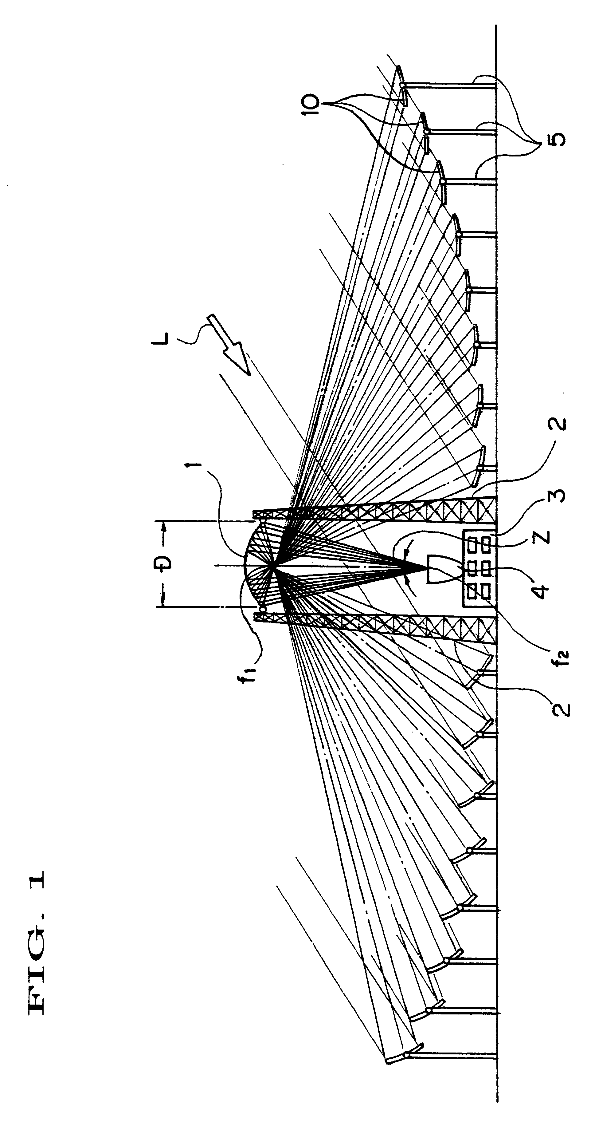
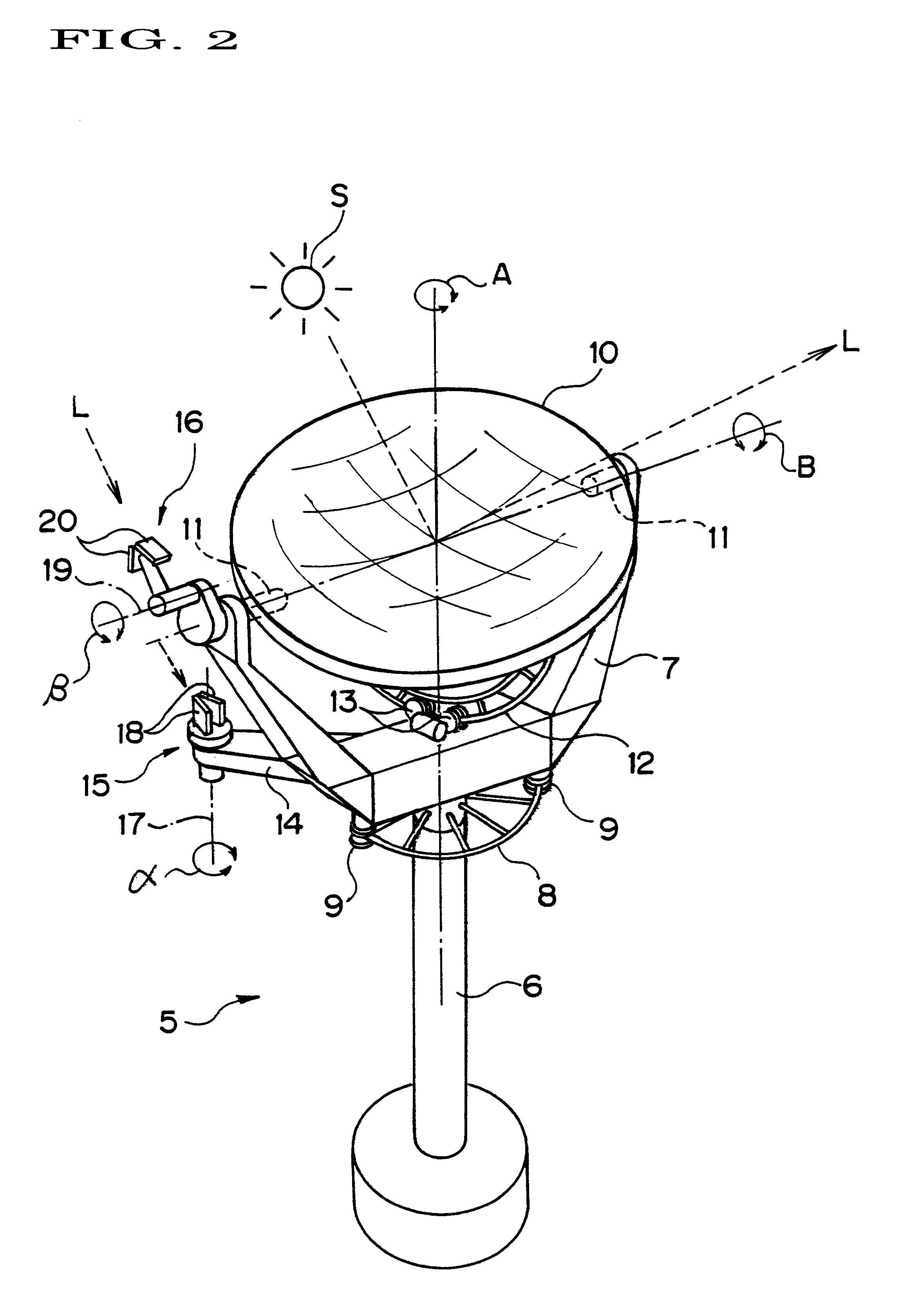
A preferred embodiment of the present invention will be described in reference to FIGS. 1 to 4. An oval mirror 1 is installed downwardly at a predetermined height with supporting towers 2. For the oval mirror 1, there exist a first focal point f1 and a second focal point f2 as "light-collecting points" below the oval mirror 1. A heat-exchange facility 3 for converting sunlight L into thermal energy is built below the oval mirror 1. On the top of the heat-exchange facility 3, a cylindrical condenser mirror 4 is mounted. A plurality of heliostats 5 are provided on the ground around the heat-exchange facility 3, surrounding the oval mirror 1.

On the top of a column 6 of the heliostat 5, a fork 7 rotatable in an azimuth direction A (See FIG. 2) is mounted. An annular link 8 is provided about the column 6. On an opposite position across the column 6 of the fork 7, a pair of upper and lower rotary pulleys 9 are provided in the downward direction. Between the pair of upper and lower rotary ...


PUM


Abstract

An azimuth sensor unit 15 and an altitude sensor unit 16 have pairs of optical sensors 18 and 20, respectively, disposed along their respective directions, which pair of optical sensors are disposed toward the sun in the form of a tapered section narrower to the front end and broader to the rear end with their light-receiving surfaces outward, and the azimuth sensor unit and the altitude sensor unit themselves rotate so as to balance light-receiving amounts of their respective pairs of optical sensors and send signals for rotating a concave mirror 10 in the same directions by half the amounts of the rotations of the azimuth sensor unit and the altitude sensor unit to a drive mechanism.

Description

1. Field of the InventionThis invention relates to a heliostat used for a sunlight collecting system that utilizes sunlight as energy.2. Prior ArtFor the global environment, the CO.sub.2 problem is so serious that the present social system relying heavily on petroleum energy is a great concern for every country. In this context, as clean energy not affecting the environment, solar energy has attracted much attention. Particularly in countries in desert areas, projects for collecting solar energy to obtain huge energy have proceeded.Those projects, however, have not gotten good results in performance and costs. The reason is that in order to utilize sunlight as energy, it is required to concentrate sunlight into a point to convert it into thermal energy and then to convert the thermal energy into electricity, in which there is difficulty in controlling heliostats for concentrating the sunlight into the point. The heliostats are arranged in large numbers around a light-collecting poin...

Claims


Application Information

Patent Timeline
Patent Type & Authority Patents(United States)
IPC IPC(8): F24J2/12F24J2/06F24J2/00F24J2/54F24J2/38G02B7/182F24S23/71F24S50/20G02B7/183
CPCF24J2/12F24J2/38F24J2/542G02B7/1827G02B7/183F24J2/523Y02E10/42Y02E10/47F24S23/71F24S25/10F24S30/452F24S50/20Y02E10/40
Inventor NAKAMURA, KATSUSHIGE
Owner MITAKA KOHKI
Why Eureka
Try Eureka