No other prior art appears to utilize the balls to optically concentrate or focus the
sunlight by using a process of
refraction within the twisting balls.
Furthermore, the prior art neither teaches or anticipates our application of adaptive transmission-mode solar tracking.
From the point of view of this patent the more recent prior art patent applications related to
solar energy concentration using rotating optical devices are significant, however, they have many disadvantages as are considered in detail below.
However, the disadvantages listed below are especially pertinent with regard to the inventions of Mario Rabinowitz et. al. and Toshiro Higuchi et. al., which are explicitly listed later in this docume
The first
disadvantage of the prior art is that it mimics the functionality of large curved surface reflectors, such as mirrored parabolic concentrators, which require a mast structure at the focal point to hold the
receiver and collect the concentrated solar
radiation.
This mechanical mast structure adds to the balance of systems costs for the system and is not compatible with compact integrated solar energy collection, concentration, and distribution devices.
The second
disadvantage of the prior art is that the mirror technology used is based on thin metallic films which are sandwiched between an upper and lower hemisphere of transparent
dielectric.
These metallic films are very difficult to manufacture with low ohmic losses.
The result is that any practical metallic mirror will typically have losses that can range from about 2% to 20% depending on the process used and the resulting purity of the
metal and it's
surface roughness.
The lower loss mirrors cost significantly more to fabricate, especially when incorporated into very small
dielectric balls or cylinders.
A third
disadvantage of the prior art is that the metallic mirrors also interact with the switching electric fields to produce ohmic losses via eddy currents.
Although the
power loss in an individual twisting ball is tinny, the total loss from many millions of twisting balls can be quite large.
This reduces the efficiency of the overall solar harvesting process.
A fourth, and extremely significant, disadvantage of the prior art is that the reflection mode operation has an intrinsic shadow loss directly related to the use of a mirror.
A fifth disadvantage of the prior art utilizing reflection mode
optics is that it cannot be integrated in intimate contact with other optical devices because the input surface and the output surface are the same.
Hence, the inclusion of, for example, an optical output lens directly on top of the reflection mode array would interfere with the input of the light.
A sixth disadvantage of the prior art is that it requires significant currents to induce the required electric fields to twist large numbers of balls and embedded mirrors over large distances.
Furthermore, because all the driving electrodes are typically quite far from the moving structures large
voltage supplies are required.
A seventh disadvantage of the prior art is that it does not adequately address the problem of pointing accuracy or pointing precision.
Pointing accuracy is related to the absolute error in solar tracking and pointing precision is related the relative error in solar tracking.
The accuracy and the precision of orientating balls or cylinders, and hence redirecting light, directly impacts the performance of the subsequent solar concentration process due to the limitations imposed by the principle of conservation of etendue—which is based on a
phase space approach to light focusing dynamics.
This discrete nature of reflection mode twisting balls and cylinders tends to limit the maximum achievable concentration when arrays of twisting structures attempt to directly focus light to a common focal point directly.
An eighth disadvantage of the prior art, especially with regard to electrostatic motors, is that it shows electrostatic stepping-motor actuation based on three or more phases of interdigitated electrodes on a single
stator.
A ninth disadvantage of the prior art, especially with regard to electrostatic motors, is that it shows electrostatic stepping-motors that do not optimally utilize the
electrode geometry.
The prior art does not achieve this theoretical limit and therefore wastes precious area resources needlessly.
A tenth disadvantage of the prior art, especially with regard to electrostatic motors, is that the multi-phase nature of the
electrode voltage distributions necessitates the use of complex geometries to make the electronic connections.
An eleventh disadvantage of the prior art, especially with regard to electrostatic stepping motors, is that it does not integrate
optics into the functionality of the
stator, rotor, or slider.
A twelfth disadvantage of the prior art in electrostatic stepping motors is that the electrical interconnections of three of more phases of belt-like electrodes requires that the electrical interconnections are distributed on more than one layer of
dielectric.
This requires complex fabrication and introduces the possibility for electrical cross talk in an environment of high voltages that are typical in
electrostatic motor design.
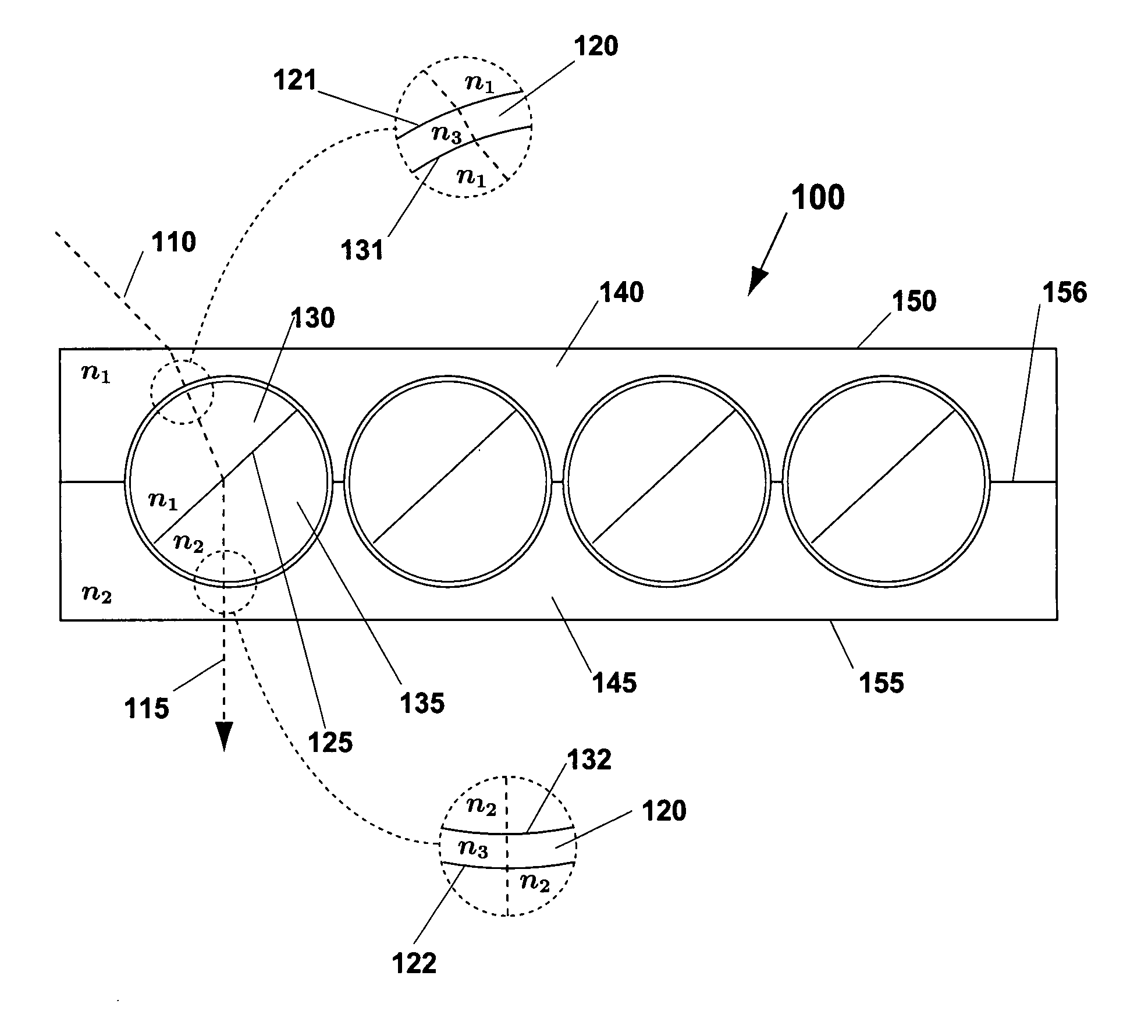
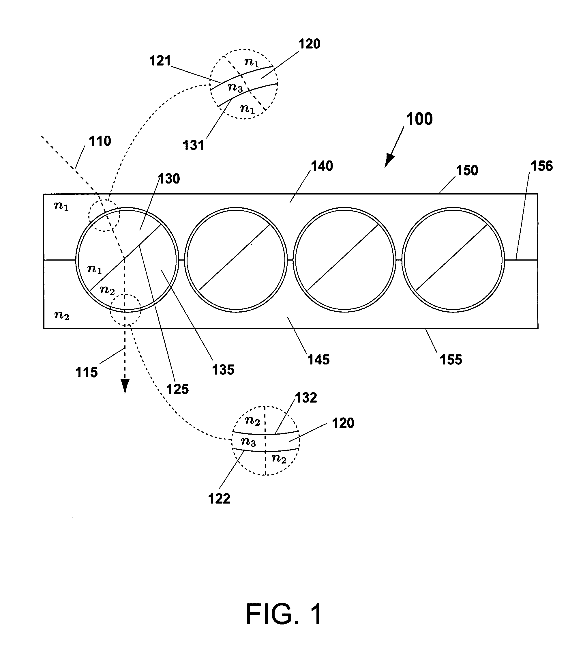
Furthermore, the prior art neither teaches nor anticipates the use of twisting ball or cylinder technology for
solar energy conversion applications.
Furthermore, the prior art neither teaches or anticipates the use of twisting ball or cylinder technology as a means to functionally separate
solar energy harvesting into four distinct steps: collection, concentration, distribution, and energy conversion.
These patents clearly do not anticipate, or show in any way, the use of a
refraction mode twisting balls and twisting cylinders for solar tracking and concentration.
There are also serious disadvantages and fundamental distinctions of kind associated with other patents that use twisting balls in display technology.
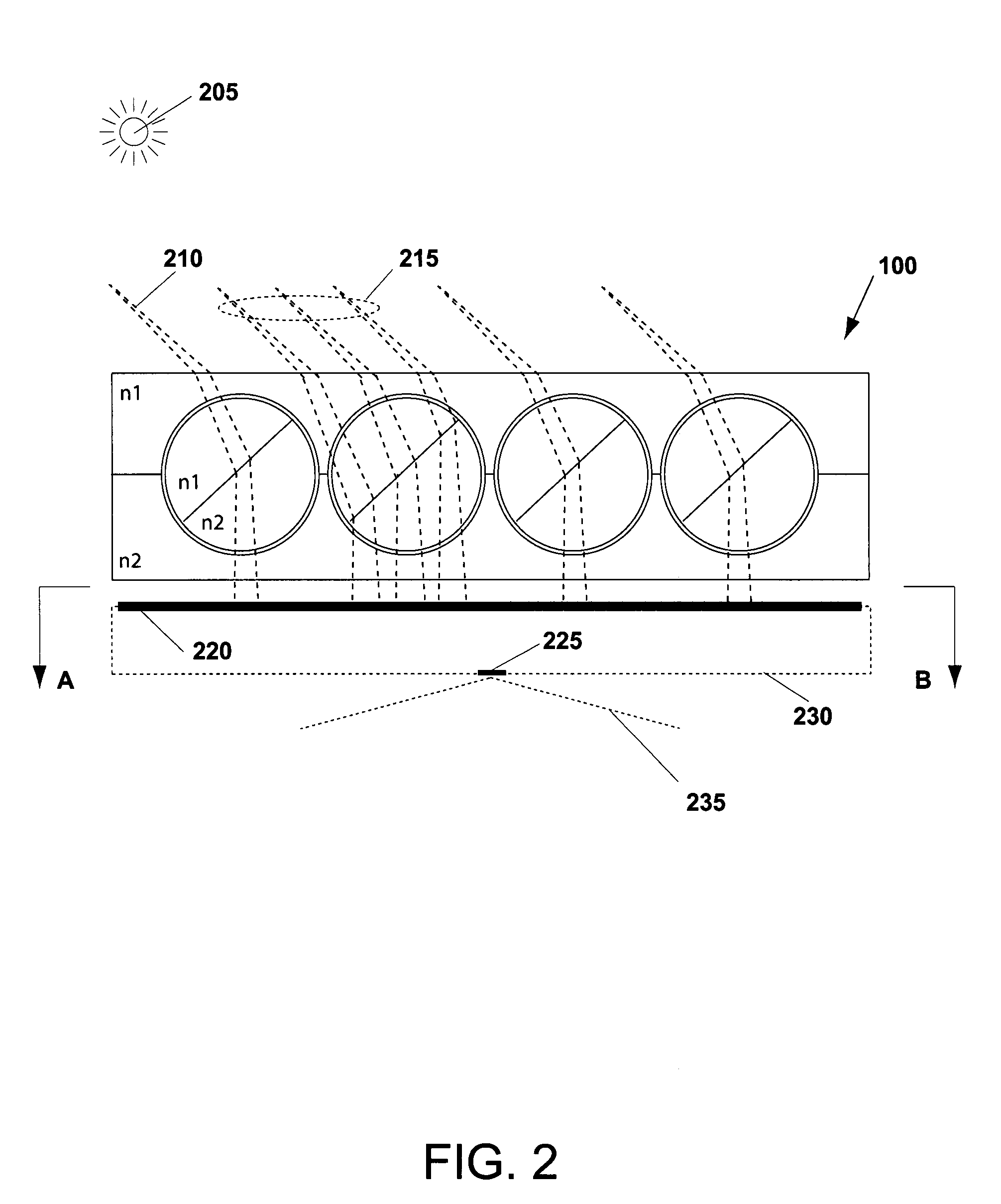
Furthermore, the prior art neither teaches nor anticipates the use of optical transmission mode twisting ball or cylinder technology in for
solar energy conversion applications.
There are also serious disadvantages in the prior art of electrostatic motors.
The prior art is either too complex, or does not have sufficient resolution for high-performance concentration.
Additionally, there are a large number of prior art electrostatic actuation devices but most of these are based on electrodes on both the
stator and the rotor; additional deficiencies of the prior art include complexity due to a need to suppress a bi-
stable state that makes direction of motor displacement impossible to determine without a means to force a predetermined direction of motion.

