

Suction port body for vacuum-cleaner and vacuum-cleaner having the same
a technology of vacuum cleaner and suction port, which is applied in the direction of vacuum cleaners, cleaning equipment, domestic applications, etc., can solve the problem that the cleaning efficiency cannot be lowered
- Summary
- Abstract
- Description
- Claims
- Application Information
AI Technical Summary
Benefits of technology
Problems solved by technology
Method used
Image

Examples
first embodiment
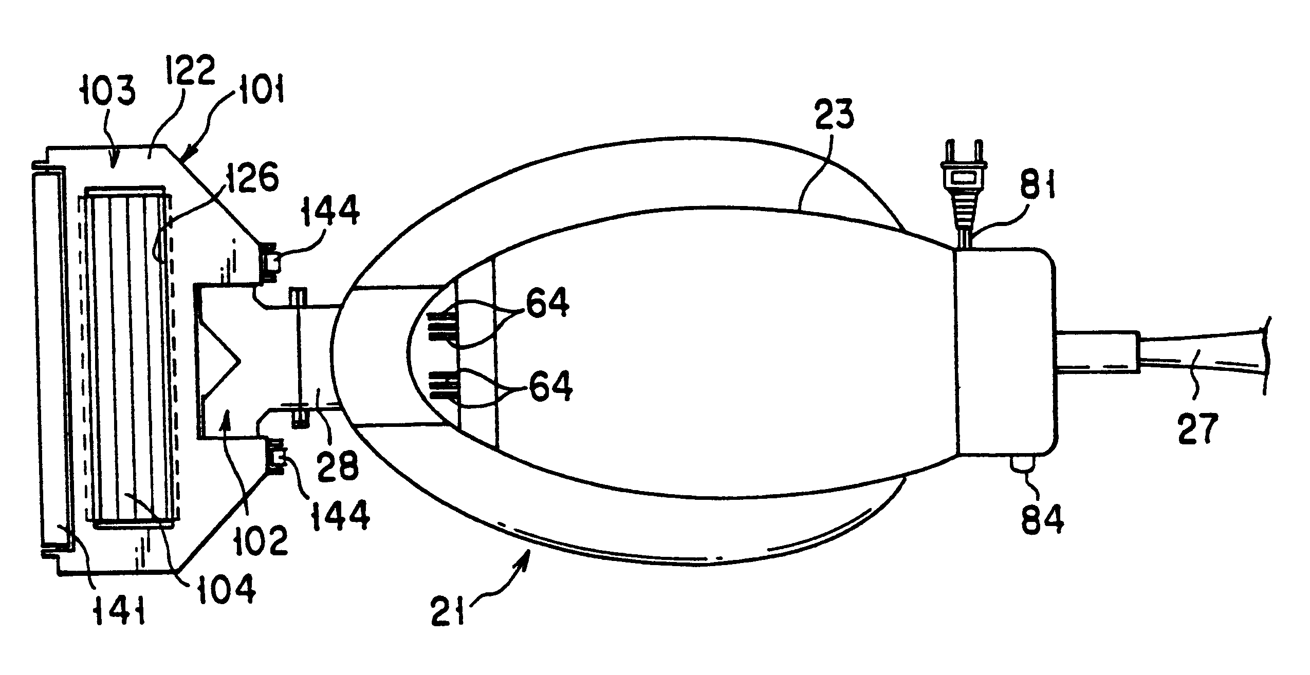
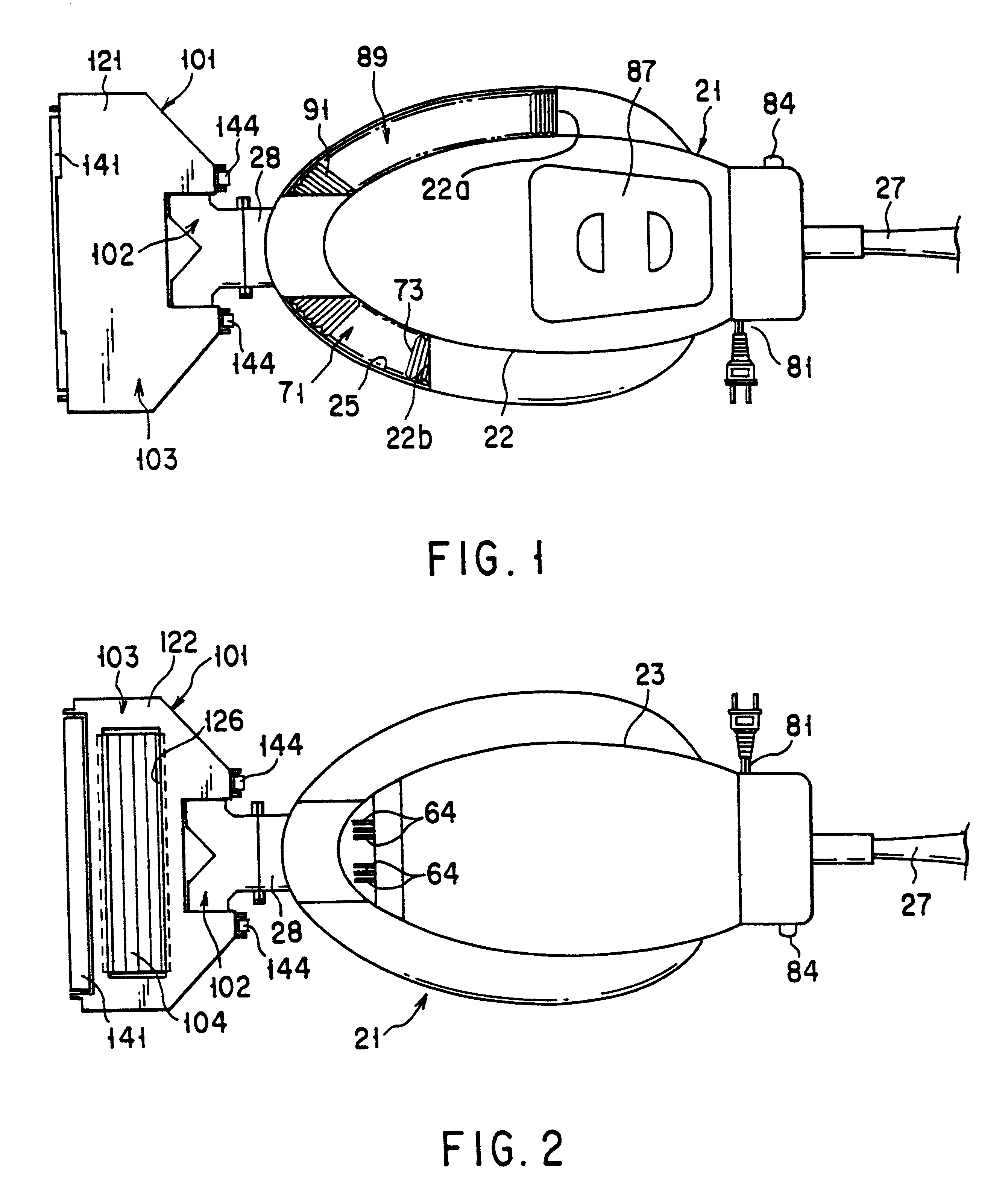
Embodiments of the present invention will now be described with reference to the drawings. FIGS. 1 to 10 show the present invention such that the present invention is applied to a so-called upright vacuum cleaner in which a suction nozzle and a cleaner body are connected directly to each other.
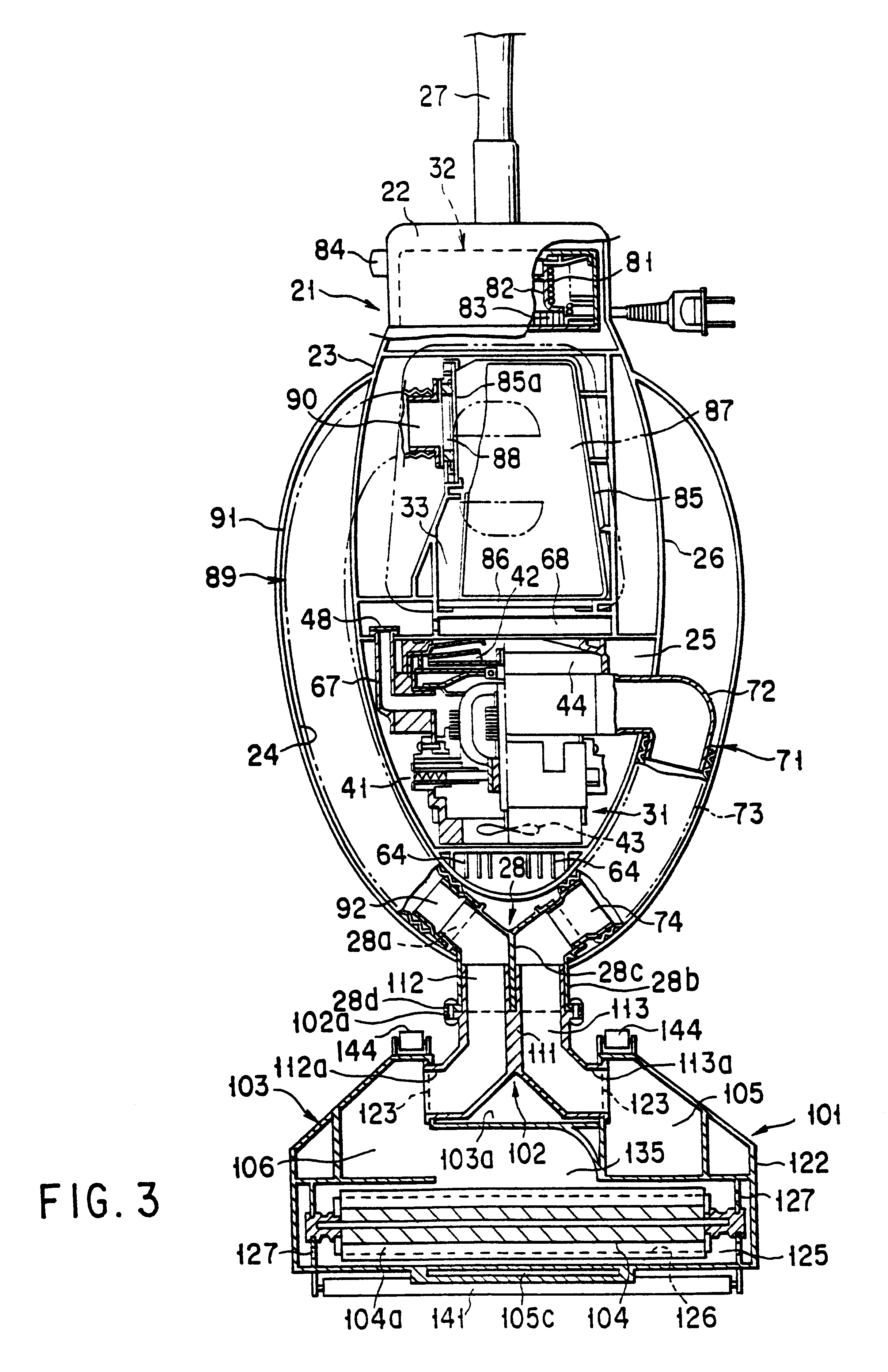
The cleaner body, which is denoted by numeral 21 in FIGS. 1, 2 and 4, is formed by connecting upper and lower plastic casings 22 and 23 by means of screws or the like. In the cleaner body 21, as shown in FIG. 3, an outer storage section 24, substantially U-shaped in this drawing, and an inner storage section 25 inside the same are divided by a U-shaped partition wall 26. One end portion of the partition wall 26 projects upward in FIG. 3, and a handle 27 for operation protrudes from a wall at the extreme end of the wall 26. As shown in FIG. 1, the upper casing 22 is provided with a pair of notches 22a and 22b. Part of the outer storage section 24 is exposed through the longer notch 22a, and par...
third embodiment
Referring now to FIGS. 13 to 16, there will be described the present invention. This is of a so-called canister type such that the cleaner body and the suction nozzle are connected by means of a flexible hose or the like. In this case, a screen portion is formed around the suction port of the suction nozzle, whereby air is prevented from leaking out.
In FIGS. 13 and 14, 320 denotes a vacuum cleaner body. The body 320 is provided inside with a dust chamber 321, a motor blower 322 for adjusting the dust chamber 321 to a negative pressure, and an exhaust chamber 323 into which air is discharged from the motor blower 322. The dust chamber 321 is fitted with a dust filter 324, and a connecting section 331 of a hose 330 is removably connected to a connecting port 325 in the body 320.
The hose 330 has a dual structure including an exhaust hose 333 and a suction hose 334 fitted therein. When the hose 330 is connected to the connecting port 325, the suction hose 334 communicates with the dust ...
fourth embodiment
Referring now to FIGS. 17 to 23, there will be described the present invention. This embodiment is applicable to a so-called "pickax" or a tubular suction nozzle that is used to clean narrow areas.
The suction port of the suction nozzle of this type has so small a diameter that it allows the circulating air to leak out easily, as mentioned before.
A vacuum cleaner of this embodiment is of a so-called upright type such that its body and the suction nozzle are connected directly to each other. The vacuum cleaner body according to this embodiment is constructed in the same manner as the one according to the first embodiment described above. In FIGS. 17 and 23, like numerals refer to portions that have their respective counterparts in the first embodiment, and a repeated description is omitted.
According to this embodiment, the interconnector pipe 28 of the cleaner body 21 is removably connected with the aforementioned suction nozzle (not shown) of a so-called floor-brush type, which is no...
PUM
 Abstract
Description
Claims
Application Information