Spray head cleaning device of 3D printing device

A cleaning device, 3D printing technology, applied in coating devices, 3D object support structures, manufacturing converters, etc., can solve the problems of wasting time and printing materials, damage to the machine, nozzle blockage, etc., and achieve the effect of efficient and convenient cleaning

Inactive Publication Date: 2019-04-16
NANTONG INST OF TECH
View PDF6 Cites 5 Cited by
  • Summary
  • Abstract
  • Description
  • Claims
  • Application Information

AI Technical Summary

Problems solved by technology

Although the failure rate of the digital operation mode is extremely low, once a failure occurs, it will not only affect the printing quality, but also waste time and printing materials, and even damage the machine. At present, the most common failure of 3D printers is nozzle clogging

Method used


Image

  • Spray head cleaning device of 3D printing device
  • Spray head cleaning device of 3D printing device
  • Spray head cleaning device of 3D printing device

Examples


Embodiment

[0030] The following is attached Figure 1-8 The present invention is described in further detail.

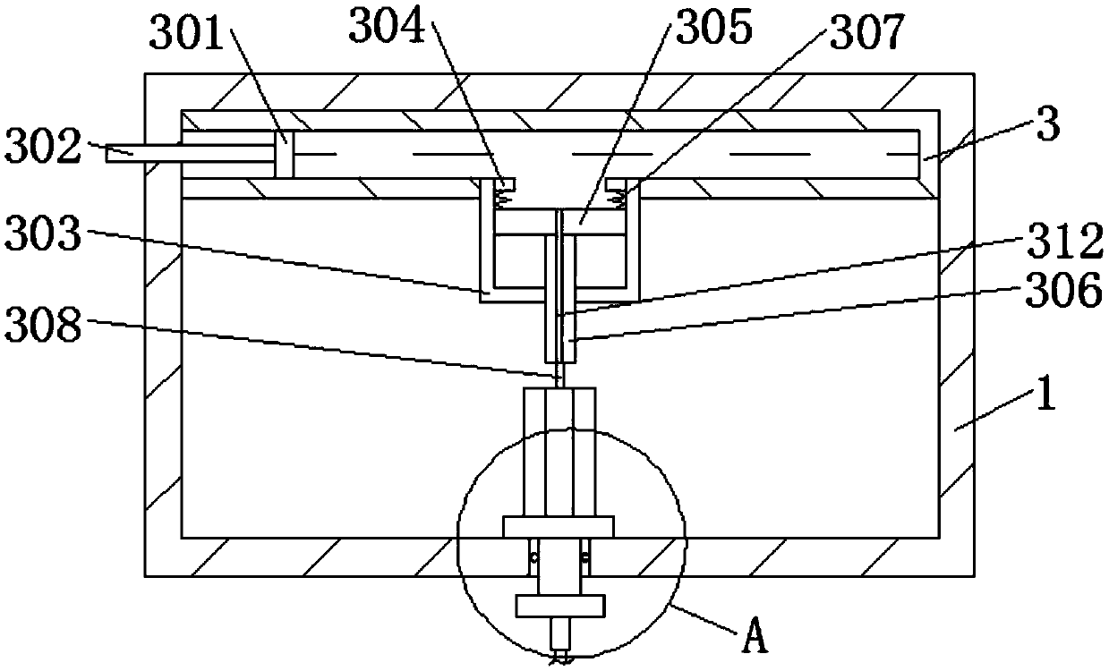
[0031] A 3D printing device nozzle cleaning device, such as Figure 1-8 As shown, it includes a cleaning box 1, the cleaning box 1 is hinged with a cleaning box door 2, and the inside of the cleaning box 1 is provided with a cleaning device.

[0032] The cleaning device comprises a fuel tank 3, which is fixedly connected with the inner top wall of the cleaning tank 1, the inner wall of the fuel tank 3 is slidingly connected with a first piston 301, and one end of the first piston 301 is fixedly connected with a first piston rod 302, and the first piston rod One end of 302 runs through the inner wall of cleaning tank 1 and extends to the outer end of cleaning tank 1. The lower end of fuel tank 3 is fixedly connected with auxiliary fuel tank 303, and the inner walls of both sides of auxiliary fuel tank 303 are fixedly connected with fixed blocks 304. The second piston 305 has a...

Embodiment 1

[0042] A 3D printing device nozzle cleaning device, such as Figure 1-8 As shown, it includes a cleaning box 1, the cleaning box 1 is hinged with a cleaning box door 2, and the inside of the cleaning box 1 is provided with a cleaning device.

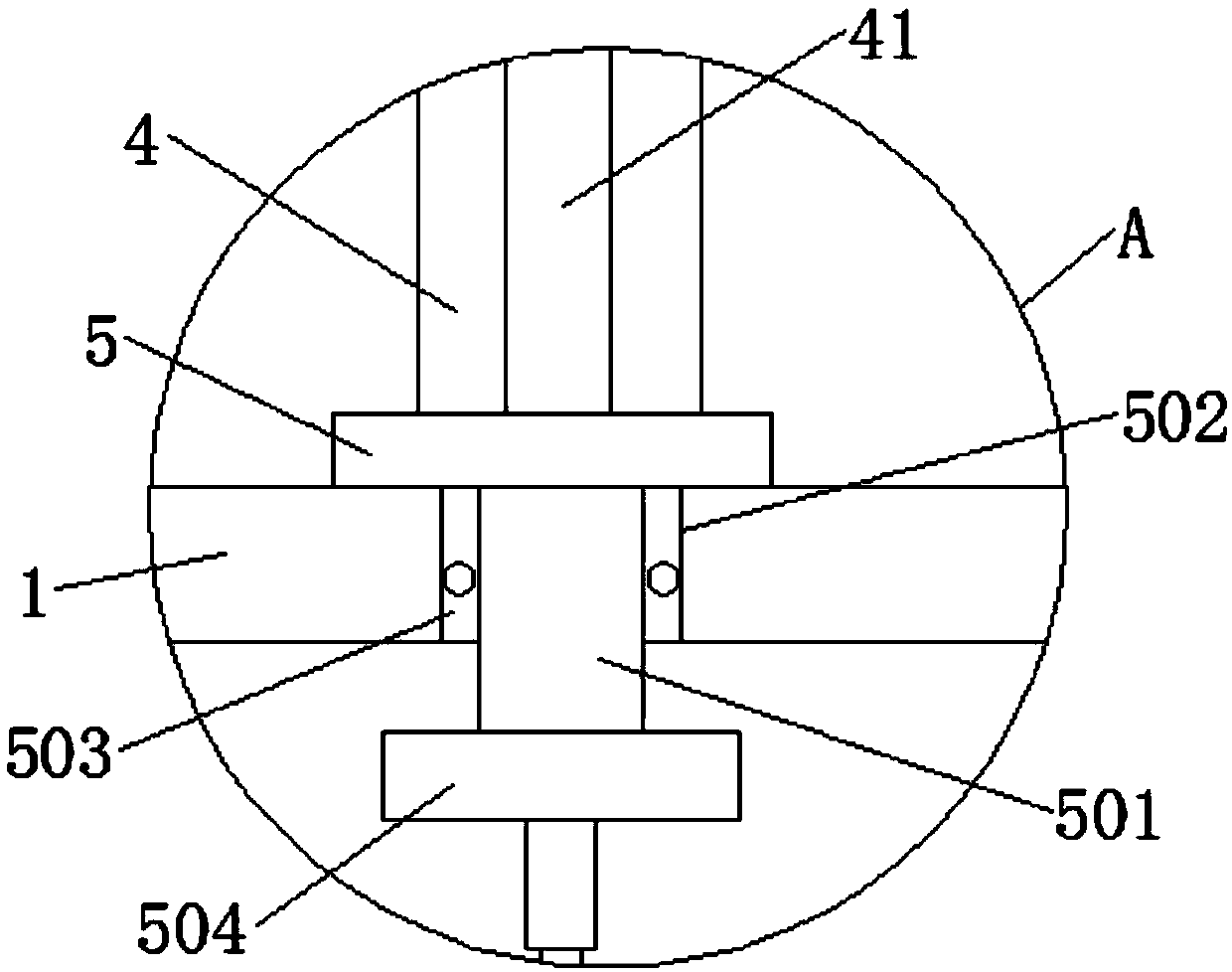
[0043] The cleaning device comprises a fuel tank 3, which is fixedly connected with the inner top wall of the cleaning tank 1, the inner wall of the fuel tank 3 is slidingly connected with a first piston 301, and one end of the first piston 301 is fixedly connected with a first piston rod 302, and the first piston rod One end of 302 runs through the inner wall of cleaning tank 1 and extends to the outer end of cleaning tank 1. The lower end of fuel tank 3 is fixedly connected with auxiliary fuel tank 303, and the inner walls of both sides of auxiliary fuel tank 303 are fixedly connected with fixed blocks 304. The second piston 305 has a second piston rod 306 fixedly connected to its lower end, and one end of the second piston rod 306 pen...

Embodiment 2

[0053] A 3D printing device nozzle cleaning device, such as Figure 1-8 As shown, it includes a cleaning box 1, the cleaning box 1 is hinged with a cleaning box door 2, and the inside of the cleaning box 1 is provided with a cleaning device.

[0054] The cleaning device comprises a fuel tank 3, which is fixedly connected with the inner top wall of the cleaning tank 1, the inner wall of the fuel tank 3 is slidingly connected with a first piston 301, and one end of the first piston 301 is fixedly connected with a first piston rod 302, and the first piston rod One end of 302 runs through the inner wall of cleaning tank 1 and extends to the outer end of cleaning tank 1. The lower end of fuel tank 3 is fixedly connected with auxiliary fuel tank 303, and the inner walls of both sides of auxiliary fuel tank 303 are fixedly connected with fixed blocks 304. The second piston 305 has a second piston rod 306 fixedly connected to its lower end, and one end of the second piston rod 306 pen...


PUM


Abstract

The invention discloses a spray head cleaning device of a 3D printing device. The spray head cleaning device of the 3D printing device comprises a cleaning box, a cleaning box door is hinged to the cleaning box, and a cleaning device is arranged in the cleaning box. The cleaning device comprises a fuel tank, the fuel tank is fixedly connected with the inner top wall of the cleaning box, a first piston is slidably connected to the inner wall of the fuel tank, and a first piston rod is fixedly connected to one end of the first piston. One end of the first piston rod penetrates through the innerwall of the cleaning box and extends to the outer end of the cleaning box, an auxiliary fuel tank fixedly communicates with the lower end of the fuel tank, and fixed blocks are fixedly connected to both sides of the inner walls of the auxiliary fuel tank. A second piston is slidably connected to the inner wall of the auxiliary fuel tank, and a second piston rod is fixedly connected to the lower end of the second piston. According to the spray head cleaning device of the 3D printing device, by arranging the cleaning device, a cleaning rod hooks sundries in a spray cavity and pulls back the first piston rod, under the action of a tension spring, a cleaning pipe leaves the spray cavity, the cleaning rod draws up the sundries in the spray cavity, so that the printing spray head is not prone tobeing blocked.

Description

technical field [0001] The invention relates to the technical field of 3D printers, more specifically, it relates to a nozzle cleaning device of a 3D printing device. Background technique [0002] 3D printer, also known as three-dimensional printer, is a kind of cumulative manufacturing technology, that is, a machine of rapid prototyping technology. It is based on a digital model file, using special wax, powdered metal or plastic and other bondable materials. Print layers of adhesive material to create three-dimensional objects. At this stage, 3D printers are used to manufacture products, and the technology of constructing objects by printing layer by layer. The principle of 3D printers is to put data and raw materials into 3D printers, and the machine will make products layer by layer according to the program, and the whole process is digitized. The working 3D printer has the characteristics of fast finished product and high material utilization rate. Although the failure...

Claims


Application Information

Patent Timeline
Patent Type & Authority Applications(China)
IPC IPC(8): B29C64/209B29C64/35B33Y30/00B33Y40/00C21C5/28
CPCB29C64/209B29C64/35B33Y30/00B33Y40/00C21C5/28
Inventor 林盛昌杨锋陆佳慧顾雨佳瞿麟李建良盛钰
Owner NANTONG INST OF TECH
Why Eureka
Try Eureka