
Mechanical duty rubber bellows

a technology of mechanical duty and bellows, which is applied in the direction of engine seals, elongated constructional elements, constructions elements, etc., can solve the problems of limited flexural life of bellows, early fatigue cracking, and metal bellows are limited to low frequency operation or occasional use, and achieves simple shear loading and long service life.

Inactive Publication Date: 2001-05-29
ARMSTRONG RICHARD JAMES
View PDF4 Cites 11 Cited by
  • Summary
  • Abstract
  • Description
  • Claims
  • Application Information

AI Technical Summary

Benefits of technology

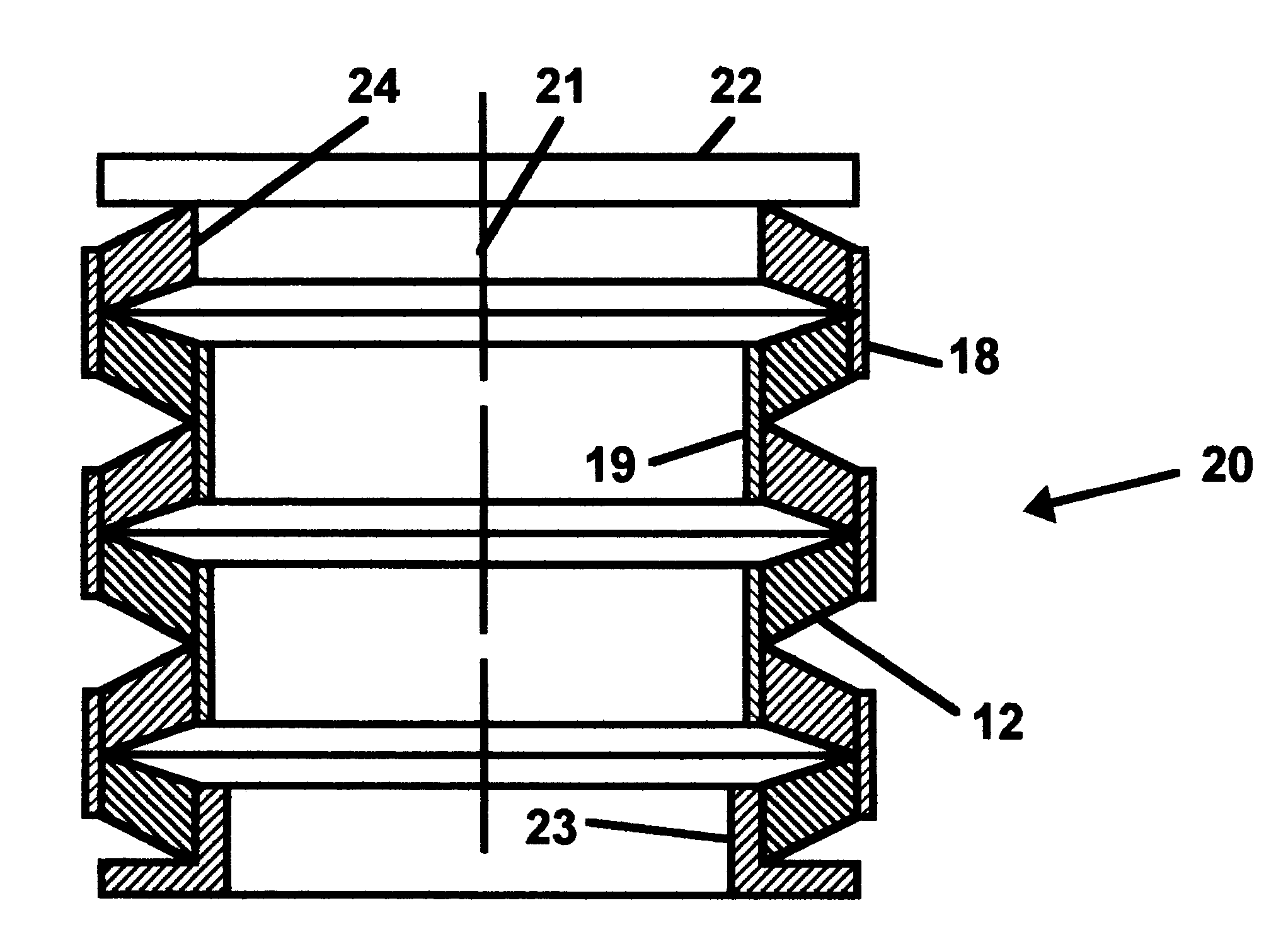
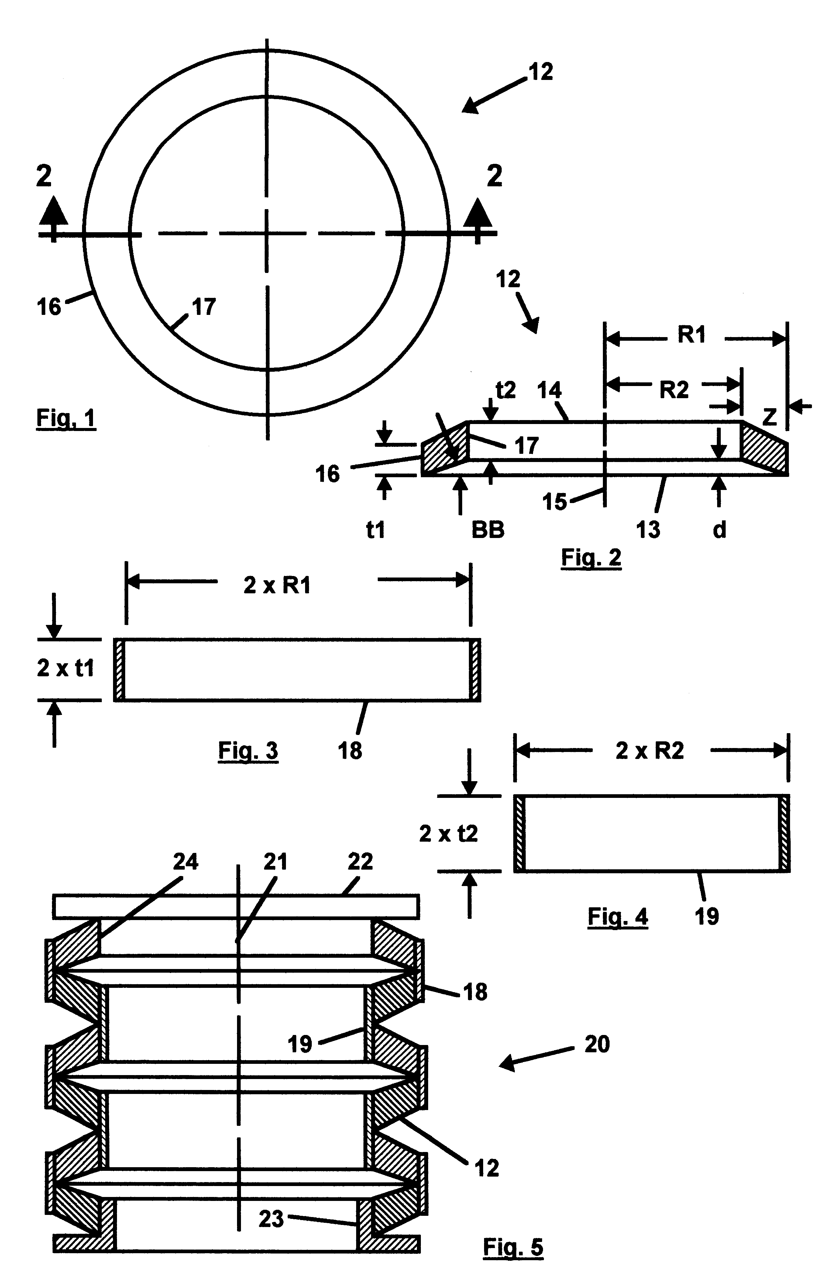
I have found that by constructing a bellows from a number of annular rubber diaphragms of comparatively thick cross-section alternately bonded to a series of outer and inner metal hoops, a dynamic seal having a long service life results. The metal hoops limit the rubber diaphragms to simple shear loading only during flexure of the bellows and since the stresses for rubber in simple shear are predictable, it is possible to calculate suitable dimensions for the diaphragms to control shear stresses within acceptable levels and a long stroke positive pressure seal having an extended service life at high reciprocating speeds is obtained.

Problems solved by technology

These bellows are of limited flexural life due to the bending of the metal at the convolutions which generates unpredictable stresses and leads to early fatigue cracking.
Metal bellows are thus limited to low frequency operation or occasional use.
A further disadvantage with metal bellows is their sensitivity to vibration which can cause premature fatigue cracking.
However this type of rubber bellows is intended for use as a dust cover and the like and is not suitable for pressure service.
Also they have the disadvantage of requiring lubrication which in some applications is objectionable.

Method used


Image

  • Mechanical duty rubber bellows
  • Mechanical duty rubber bellows

Examples


example

A bellows is required having a stroke of 1.5 inches, a diameter of not more than 3.5 inches and to operate at 100 psi internal pressure down to a vacuum of 2.7 psi absolute. The allowable shear stress on the rubber bonds is 80 psi. ps Solution:

Let diameter=3.0 inches

R1=3 / 2=1.5 inches

Select Q=0.2

Z=0.2.times.1.5=0.3 inches

R2=1.5-0.3=1.20 inches

Select B=0.4

Angle BB=arc tan0.4=21.80 degrees

Select TR=0.5

S=0.5.times.0.4 / [(sin21.8 sin(90-21.8)]=0.58

d=0.4.times.0.3=0.12 inches

t1=0.58.times.0.3=0.174 inches

t2=1.5.times.0.174 / 1.2=0.217 inches


PUM


Abstract

A mechanical duty bellows seal is constructed from a number of annular rubber diaphragms of comparatively thick cross-section alternately bonded to a series of outer and inner metal hoops so that the hoops hold the rubber diaphragms in simple shear during flexure of the bellows. The stresses in the rubber in shear are predictable thus allowing the calculation of diaphragm proportions to control stress levels.

Description

This invention relates to mechanical duty bellows employed as dynamic pressure seals where a positive seal without leakage is made between moving parts.A bellows as a dynamic or movable pressure seal is often employed for sealing a reciprocating plunger or similar device where one end of the bellows is fixed and the other attached to the moving plunger. A bellows is selected because it is leak-proof and a long stroke may be had by simply providing a sufficient number of convolutions. The flexing of the bellows is accomplished by a bending of the bellows material at the convolutions. This bending action is characteristic of all prior types of bellows.Prior types of bellows intended for such dynamic use are usually made from metal, either stretch formed from a metal tube or brazed-up from metal diaphragms. These bellows are of limited flexural life due to the bending of the metal at the convolutions which generates unpredictable stresses and leads to early fatigue cracking. Metal bell...

Claims


Application Information

Patent Timeline
Patent Type & Authority Patents(United States)
IPC IPC(8): F16J3/00F16J3/04
CPCF16J3/04
Inventor ARMSTRONG, RICHARD JAMES
Owner ARMSTRONG RICHARD JAMES
Learn More