
Device for electrically connecting a coaxial line to a printed circuit card

a technology of printed circuit card and coaxial line, which is applied in the direction of coupling device connection, coupling device details, two-pole connection, etc., can solve the problems of high manufacturing cost, complex and expensive, and inability to enable the cable to be disconnected, and achieves low cost and small volume

Inactive Publication Date: 2001-05-29
RADIALL SA
View PDF8 Cites 83 Cited by
  • Summary
  • Abstract
  • Description
  • Claims
  • Application Information

AI Technical Summary

Benefits of technology

The invention seeks to provide a device which is simple and of low cost but enables a coaxial line to be connected directly to a printed circuit card, the device also being very small in volume.
The device of the invention turns out to be particularly simple and of low cost to manufacture and to install since it is made up of only one element which is mounted directly on the card.
By means of the invention, the coaxial structure of the electric line is conserved all the way to the tracks on the card, thereby providing better impedance matching with the line.
With respect to the card, the device of the invention also presents the advantage whereby no special preparation is required for the card other than arranging the conductor tracks at the edge of the card, i.e. there is no need for any cutting, metallization, or drilling.

Problems solved by technology

Nevertheless, that method is suitable for circuits that operate at low frequency only because of the poor impedance matching that results from the soldering.
It also does not enable the cable to be disconnected.
However they are relatively complex and expensive to manufacture and they occupy considerable volume on the card, and that is not always compatible with miniaturizing the card.

Method used


Image

  • Device for electrically connecting a coaxial line to a printed circuit card
  • Device for electrically connecting a coaxial line to a printed circuit card
  • Device for electrically connecting a coaxial line to a printed circuit card

Examples


Embodiment Construction

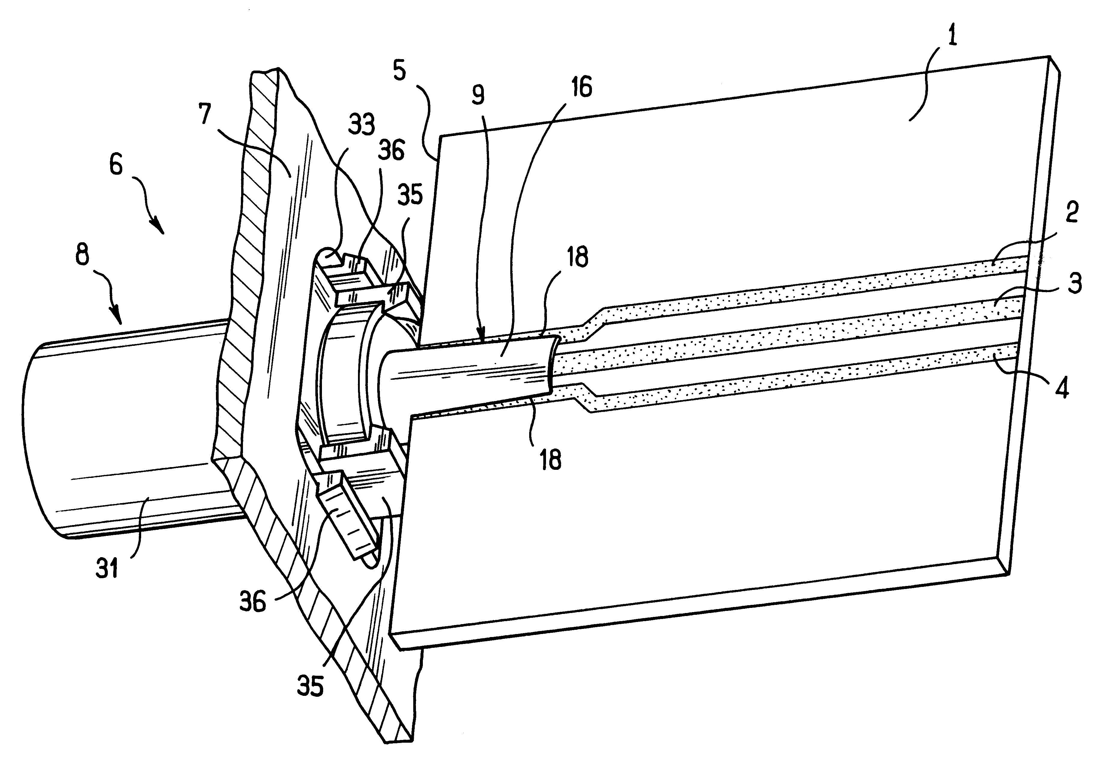
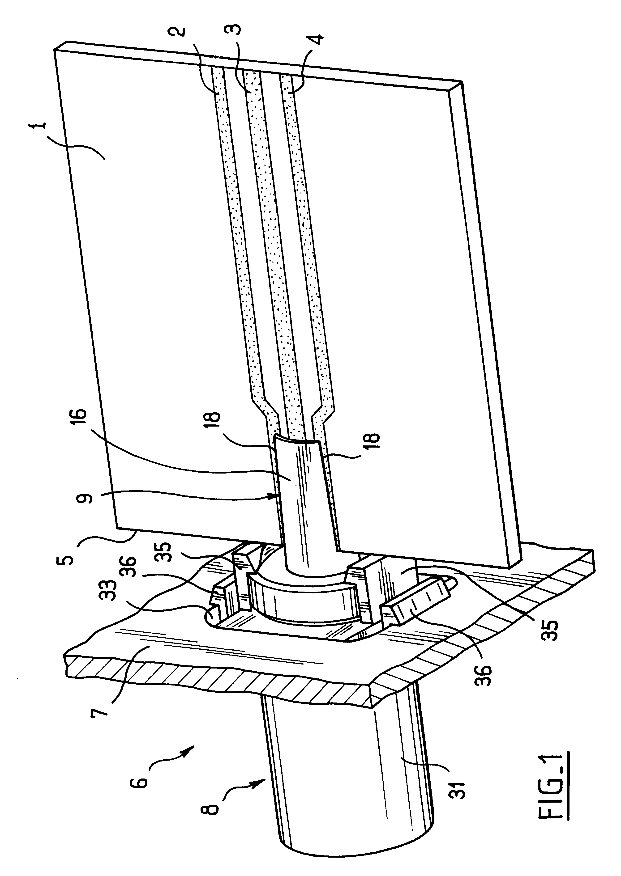
In FIGS. 1 to 8, there can be seen a printed circuit card 1 having a ribbon of three parallel conductor tracks 2, 3, 4, where the center track 3 is designed to convey an electrical signal while the tracks 2 and 4 on either side thereof are ground tracks.

The spacing between the tracks on the card is determined as a function of the impedance that is to be given to the pseudo-coaxial line they constitute.

The three tracks extend to the edge 5 of the card where they are brought closer together so that their spacing corresponds to the spacing of the connection device 6 described below.

The connection device 6 is mounted on a panel 7 (shown in part) of a housing (not shown) containing the card.

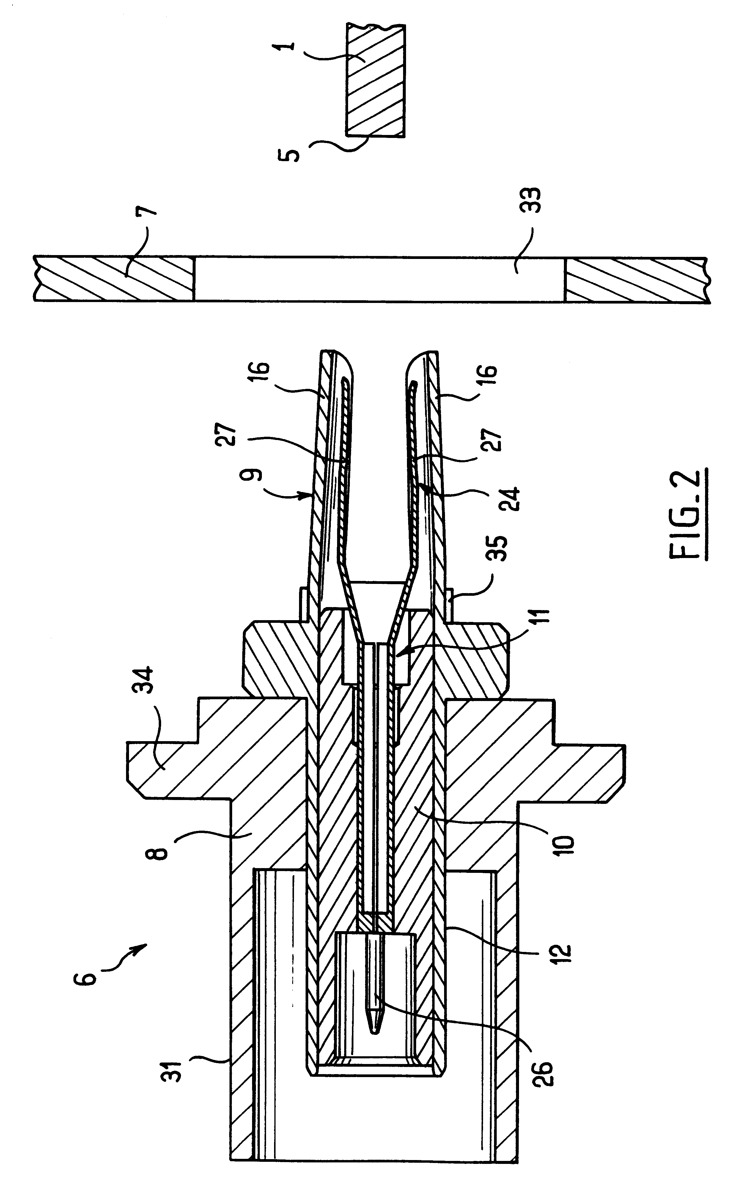
The device comprises a body 8, an outer contact 9, an insulator 10, and a center contact 11 housed inside the outer contact.

In FIG. 6, the outer contact can be seen to comprise a tubular rear portion 12 for connecting electrically to the ground contact of a coaxial connector element (not shown) to whi...


PUM


Abstract

The invention relates to a device for electrically connecting a coaxial line to a printed circuit card having at least two conductor tracks each extending to an edge of said card. The device has an outer contact and a center contact received inside the outer contact. The outer contact has a portion for connection to the card that is substantially tubular in shape, being provided with two diametrically-opposite slots which subdivide said connection portion into two jaws arranged to pinch between them said card inserted via its edge between said jaws, and the center contact has portion for connection to the card in the form of a clip into which the edge of the card is engaged when the card is inserted between the two jaws of the outer contact.

Description

The present invention relates to a device for electrically connecting a coaxial line to a printed circuit card.Various solutions have already been devised and proposed for connecting a coaxial cable to a printed circuit card.The simplest solution consists in soldering the ground conductor and the central conductor of the cable directly to corresponding tracks on the card. Nevertheless, that method is suitable for circuits that operate at low frequency only because of the poor impedance matching that results from the soldering. It also does not enable the cable to be disconnected.Connectors have also been proposed that comprise two elements, one of which is fixed to the card and the other of which is mounted on the end of the coaxial cable. Such connectors present all of the advantages of a releasable connection, and they generally provide good impedance matching for the line.However they are relatively complex and expensive to manufacture and they occupy considerable volume on the c...

Claims


Application Information

Patent Timeline
IPC IPC(8): H01R13/00H01R13/646H01R24/00H01R13/74H01R107/00
CPCH01R24/50H01R2103/00H01R12/721
Inventor BAFFERT, JEAN-MARC
Owner RADIALL SA
Learn More