Warning device for filter-changing time

a technology of filter-changing time and warning device, which is applied in the direction of separation of dispersed particles, transportation and packaging, and separation of separation processes, etc., can solve the problems of reducing changing and difficult to accurately determine the air amount passing through the filter

Inactive Publication Date: 2001-05-29
DENSO CORP
View PDF6 Cites 25 Cited by
  • Summary
  • Abstract
  • Description
  • Claims
  • Application Information

AI Technical Summary

Problems solved by technology

Because dust and smelling components are physically collected into a filter for an air conditioner, the filter is clogged with using time and using condition, and an air amount passing through the filter is decreased.
However, generally, the air amount passing through the filter is changed in accordance with a clogging degree of the filter.
Therefo

Method used


Image

  • Warning device for filter-changing time
  • Warning device for filter-changing time
  • Warning device for filter-changing time

Examples


first embodiment

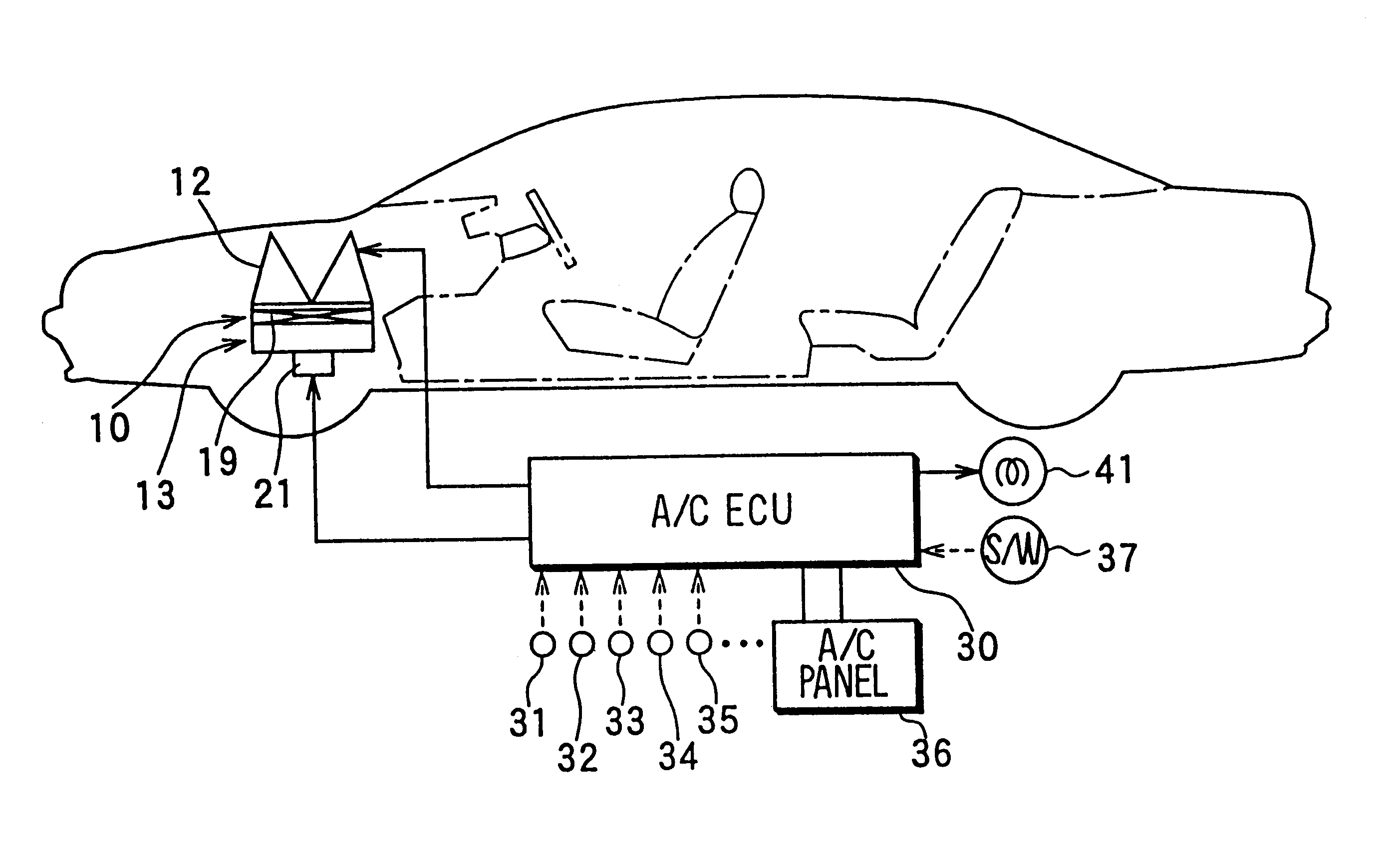
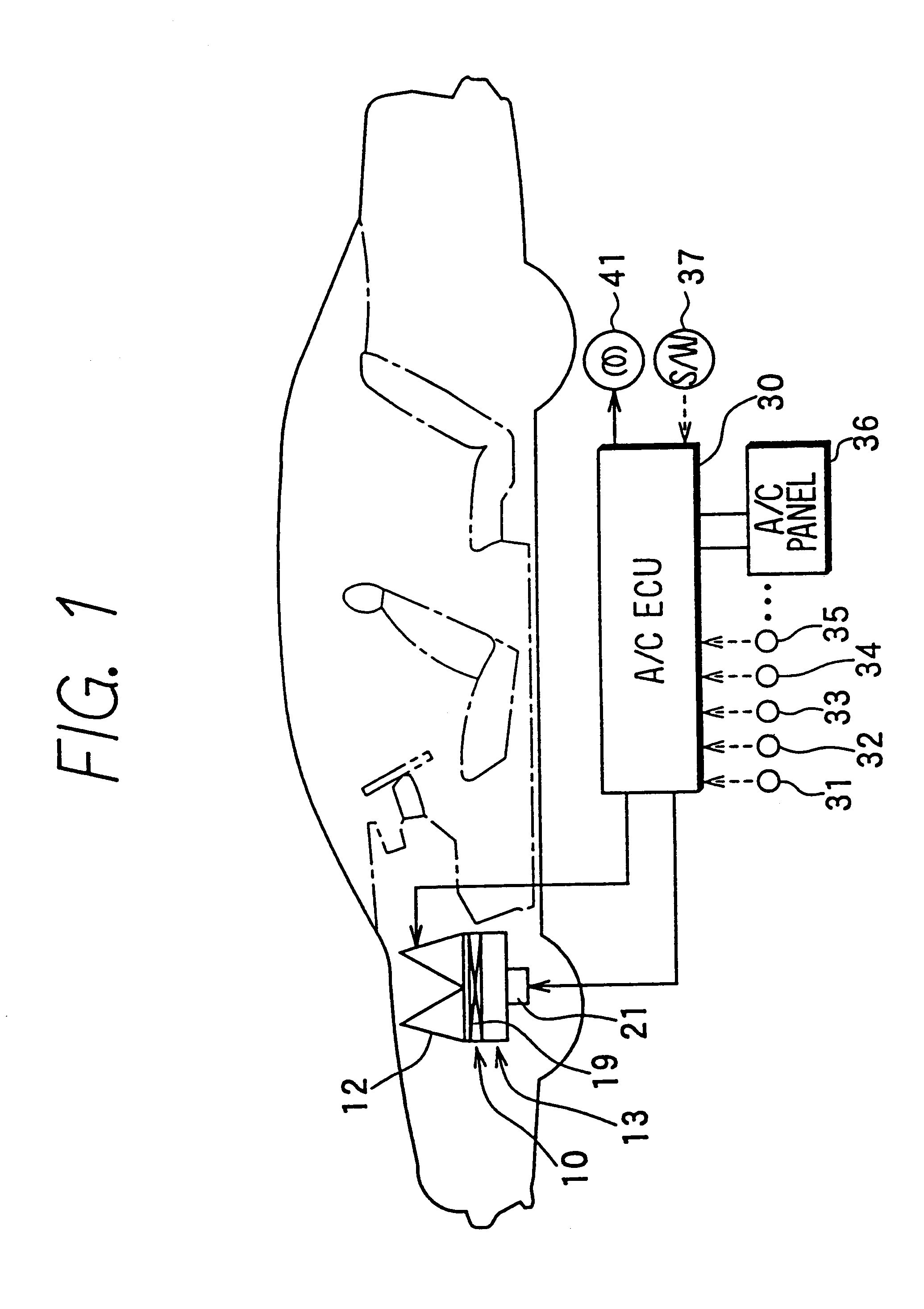
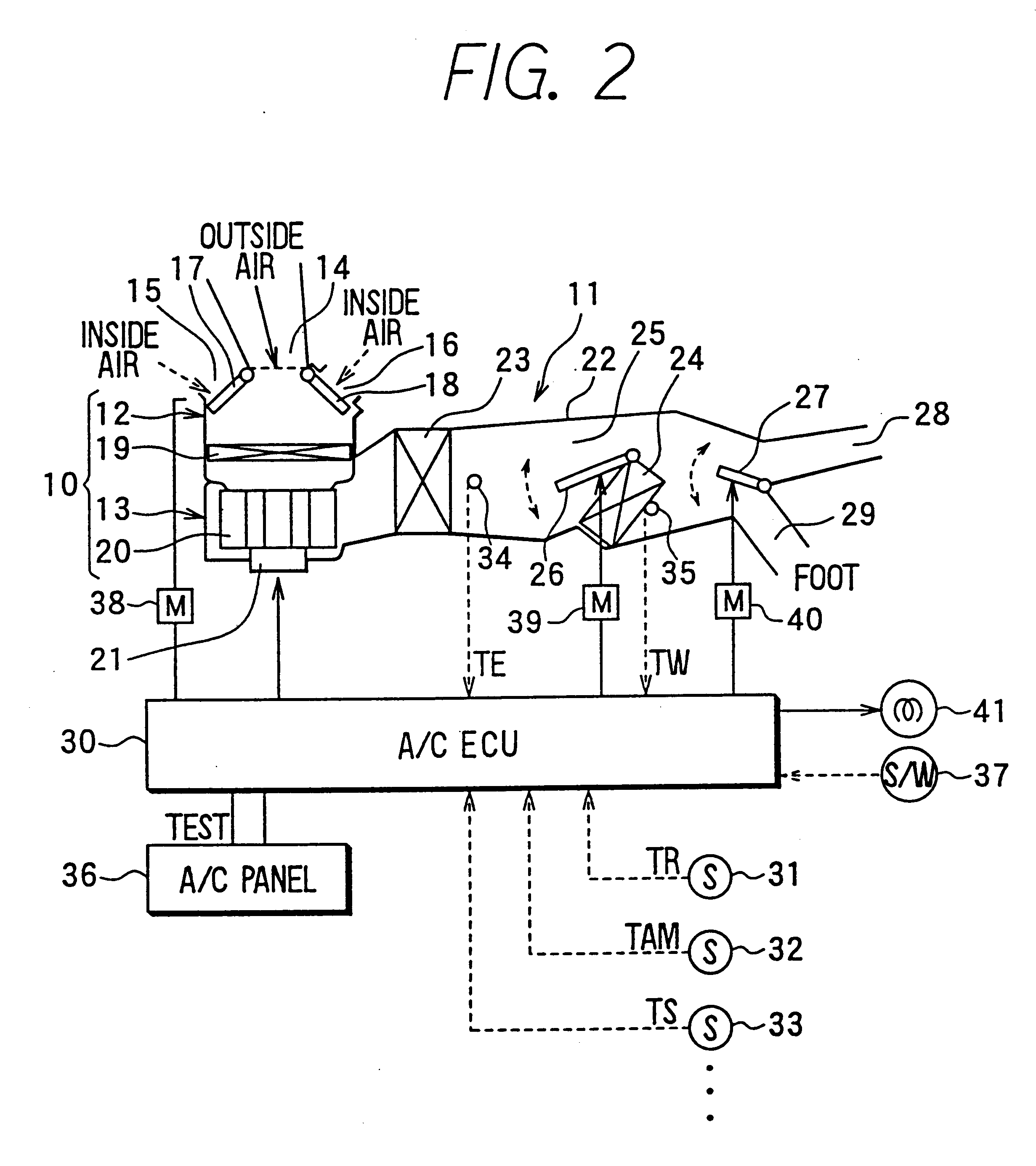
In the present invention, an operation of a driving motor 38 of the inside / outside air switching doors 17, 18, an operation of a fan driving motor 21, an operation of a driving motor 39 of the air mixing door 26 and an operation of a driving motor 40 of the air outlet mode door 27 are controlled by control signals from the ECU 30. Further, an operation of an indication lamp (warning device) 41 for indicating a warning a changing time of the filter 19 is also controlled by a control signal from the ECU 30.

In FIG. 2, the manual operation switch 37 and the indication lamp 41 are independently separately disposed from the operation panel 36. For example, the manual operation switch 37 and the indication lamp 41 can be disposed at a side of a vehicle meter. However, the manual operation switch 37 and the indication lamp 41 may be disposed on the air-conditioning operation panel 36.

Next, control operation of the indication lamp 41 according to the first embodiment will be now described wi...

second embodiment

In the second embodiment, as the filter 19 of the blower unit 10, a dust filter having a relative low pressure loss for mainly removing dust contained in air is used. On the other hand, a deodorizing filter having a relative high pressure loss for mainly deodorizing air is used as the filter 55 of the air cleaner 50. That is, in the filter 55, deodorizers (e.g., active carbon) is impregnated in a porous base material such as urethane foam by suitable binders. Here, the deodorizer-impregnated porous base material is made into a corrugated form (i.e., wave shape) to increase the filter surface area.

In the second embodiment, as shown in FIG. 4, the manual operation switch 37 and the indication lamp 41 are disposed for warning a change time of the filter 19 of the blower unit 10, while a manual operation switch 57 and an indication lamp 58 are also disposed for warning a change time of the filter 55 of the air cleaner 50. The warning control of the change time of the filter 55 is perfor...


PUM

PropertyMeasurementUnit
Temperatureaaaaaaaaaa
Timeaaaaaaaaaa

Abstract

A warning device for warning change time of a filter for cleaning air includes an indication lamp which indicates a warning of the change time of the filter, and a control unit for controlling operation of the indication lamp. The control unit sets a next timer setting value for the next filter change to a filter-using time until a change of the filter, and operates the indication lamp when the filter-using time passes the next timer setting value after the change of the filter. Thus, the warning of the change time of the filter is performed at a suitable moment reflecting a variation of a clogging degree of the filter. As a result, the warning device accurately performs the warning of the change time of the filer without using a sensor for detecting the clogging degree of the filter.

Description

This application is related to and claims priority from Japanese Patent Application No. Hei. 11-136024 filed on May 17, 1999, the contents of which are hereby incorporated by reference.1. Field of the InventionThe present invention relates to a warning device for warning a filter-changing time, which is suitably used for a vehicle air conditioner, for example.2. Description of Related ArtBecause dust and smelling components are physically collected into a filter for an air conditioner, the filter is clogged with using time and using condition, and an air amount passing through the filter is decreased. For preventing a decrease of air-conditioning capacity due to the clogging of the filter, for example, in a conventional vehicle air conditioner described in JP-A-7-81392, an air amount passing through a filter is estimated based on a rotation speed of a blower fan and a vehicle speed, and a filter-changing time is determined so that a warning signal is output.However, generally, the a...

Claims


Application Information

Patent Timeline
IPC IPC(8): B01D46/42B60H3/06B01D46/00B01D46/46
CPCB01D46/0086B01D46/46B60H3/0608B60H2003/0683
Inventor HONDA, YUJIIMAI, HIROKAZUNINOMIYA, HITOSHI
Owner DENSO CORP
Why Eureka
Try Eureka