Electronic device and filtering unit

Inactive Publication Date: 2010-03-16
CHIEN HLDG
View PDF13 Cites 26 Cited by
  • Summary
  • Abstract
  • Description
  • Claims
  • Application Information

AI Technical Summary

Problems solved by technology

Fine particles, such as dust in the air, may be, however, sucked into the electronic device, thus causing damage.

Method used


Image

  • Electronic device and filtering unit
  • Electronic device and filtering unit
  • Electronic device and filtering unit

Examples


Embodiment Construction

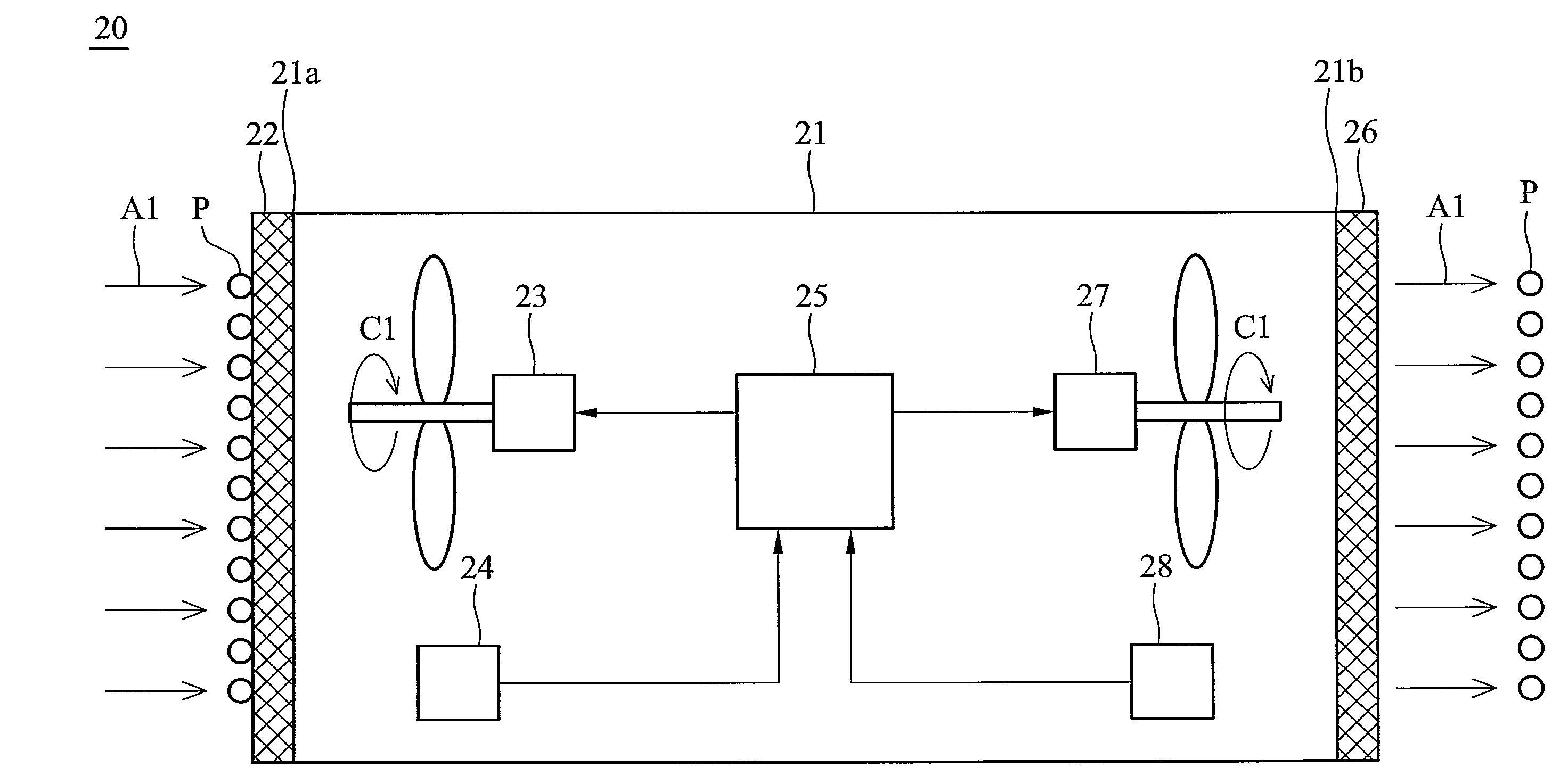
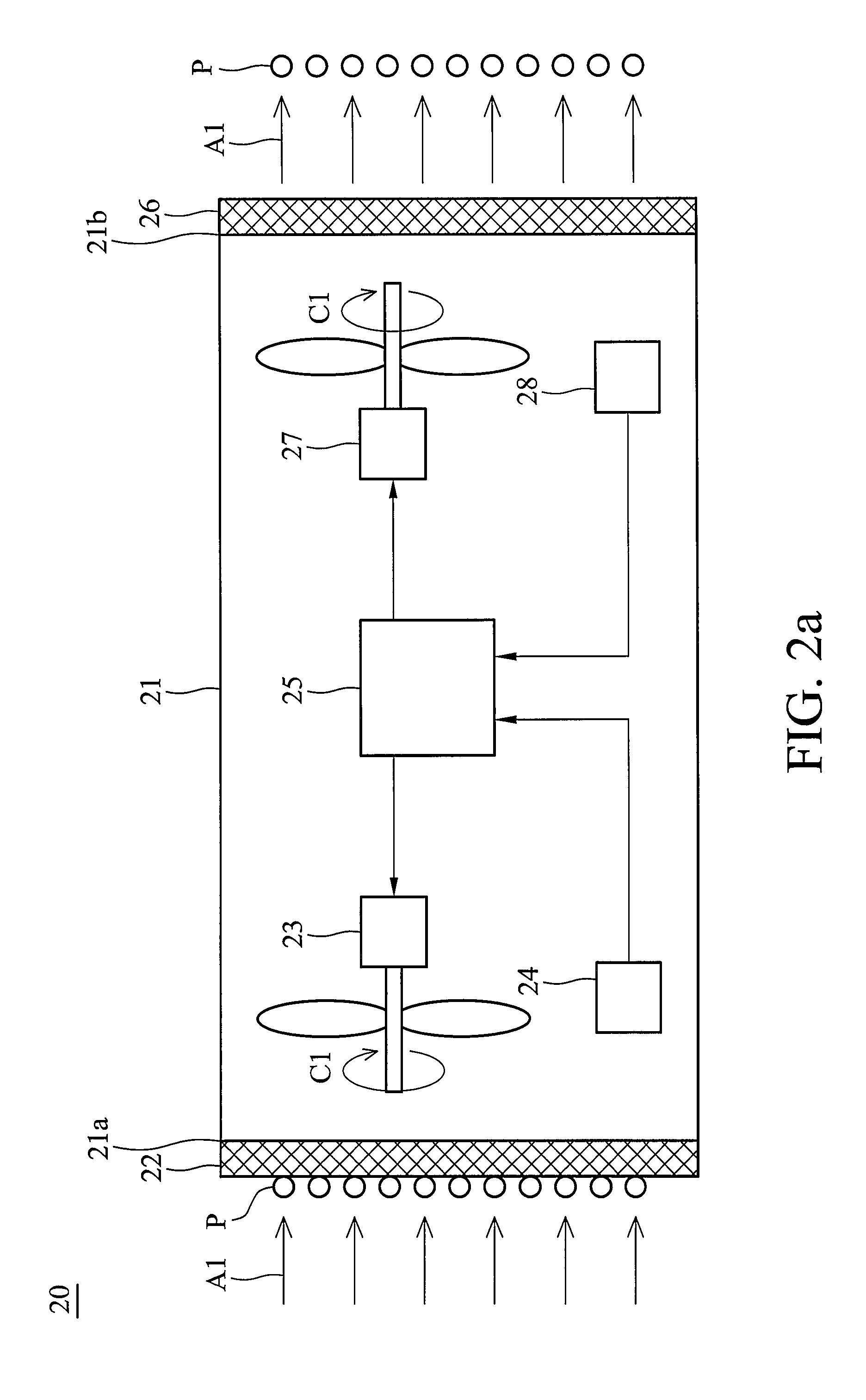
[0022]Referring to FIG. 2a, an embodiment of a filtering unit 20 of the invention receives an electronic device (not shown) therein, and comprises a housing 21, a first filter 22, a first fan 23, a first detector 24, a controller 25, a second filter 26, a second fan 27, and a second detector 28. The housing 21 comprises an inlet 21a and an exit 21b. The first filter 22 is disposed at the inlet 21a of the housing 21, and the second filter 26 is disposed at the exit 21b of the housing 21 to filter particles P in the air. The first fan 23 and the second fan 27 are disposed in the housing 21 to generate airflow.

[0023]The first detector 24 detects the number of the particles P in the first filter 22. Referring to FIGS. 3a and 3b, the first detector 24 may be transparent-type or reflective-type. FIG. 3a depicts a transparent-type detector comprising a light emitter 241 and a receiver 242. The light emitter 241 is disposed adjacent to a first side 22a of the first filter 22 to emit light. ...


PUM

PropertyMeasurementUnit
volumeaaaaaaaaaa
thresholdaaaaaaaaaa
transparentaaaaaaaaaa

Abstract

A filtering unit for receiving an electronic device. The filtering unit includes a housing, a filter, a fan, a detector, and a controller. The housing includes an inlet. The filter is disposed at the inlet of the housing. The fan is disposed in the housing. The detector detects the number of particles in the filter. The controller is coupled to the fan and the detector. When the number of the particles in the filter exceeds a threshold value, the detector outputs a signal to the controller to change the rotating direction of the fan.

Description

BACKGROUND OF THE INVENTION[0001]1. Field of the Invention[0002]The present invention relates to an electronic device and a filtering unit, and in particular, to a filtering unit with a mechanism to assist in the cleaning of its filter.[0003]2. Description of the Related Art[0004]Electronic devices, such as projectors, generate heat during operation, air convection is necessary for cooling. Fine particles, such as dust in the air, may be, however, sucked into the electronic device, thus causing damage. As a result, a filtering unit for filtering fine particles is necessary.[0005]FIG. 1 is a schematic view of a conventional filtering unit 10. A filter 12 is disposed at an inlet 11a of a housing 11. A fan 13 and a device 1 to be cooled are disposed in the housing 11. The fan 13 draws the air A into the housing 11, and the filter 12 filters particles P in the air A. Since the filter 12 may be obstructed by the particles P, it must be replaced at predetermined intervals to maintain norm...

Claims


Application Information

Patent Timeline
Patent Type & Authority Patents(United States)
IPC IPC(8): H05K5/00B01D50/00G03B21/16G06F1/20
CPCH05K7/20181H05K7/20209
Inventor CHANG, CHONG-MIN
Owner CHIEN HLDG
Why Eureka
Try Eureka