Injector for medical use

a technology for injectors and medical devices, applied in the field of injectors for medical devices, can solve problems such as cartridge breakage, and achieve the effect of reducing the drawbacks

Inactive Publication Date: 2001-06-12
VILLETTE ALAIN
View PDF23 Cites 53 Cited by
  • Summary
  • Abstract
  • Description
  • Claims
  • Application Information

AI Technical Summary

Benefits of technology

The present invention thus seeks to mitigate those drawbacks. It is based on the idea that all of the forces to be transmitted need to be transmitted on the axis ...

Problems solved by technology

It is based on the idea that all of the forces to be transmitted need to be transmitted on the axis of the injector while avoiding ...

Method used


Image

  • Injector for medical use
  • Injector for medical use
  • Injector for medical use

Examples


Embodiment Construction

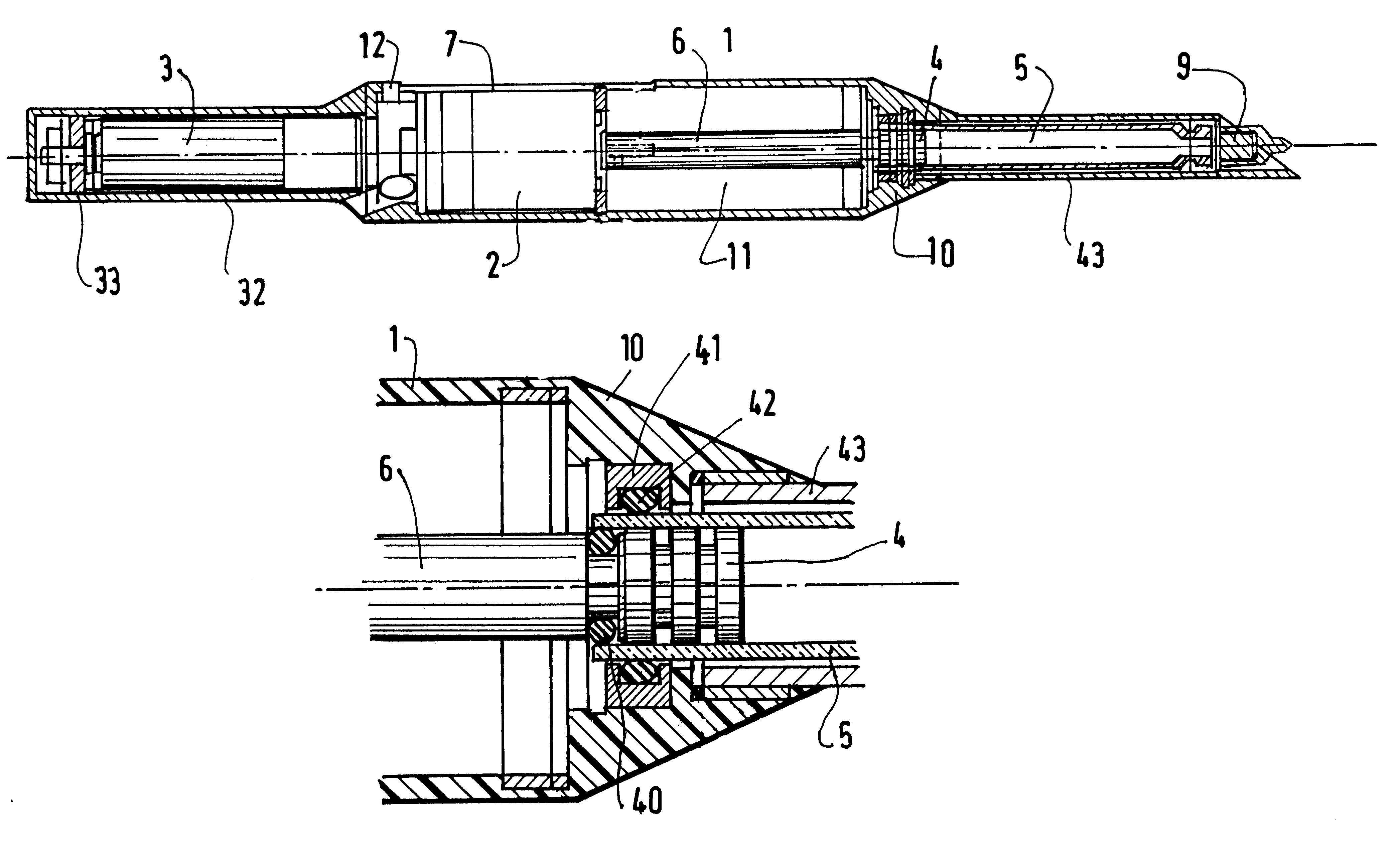
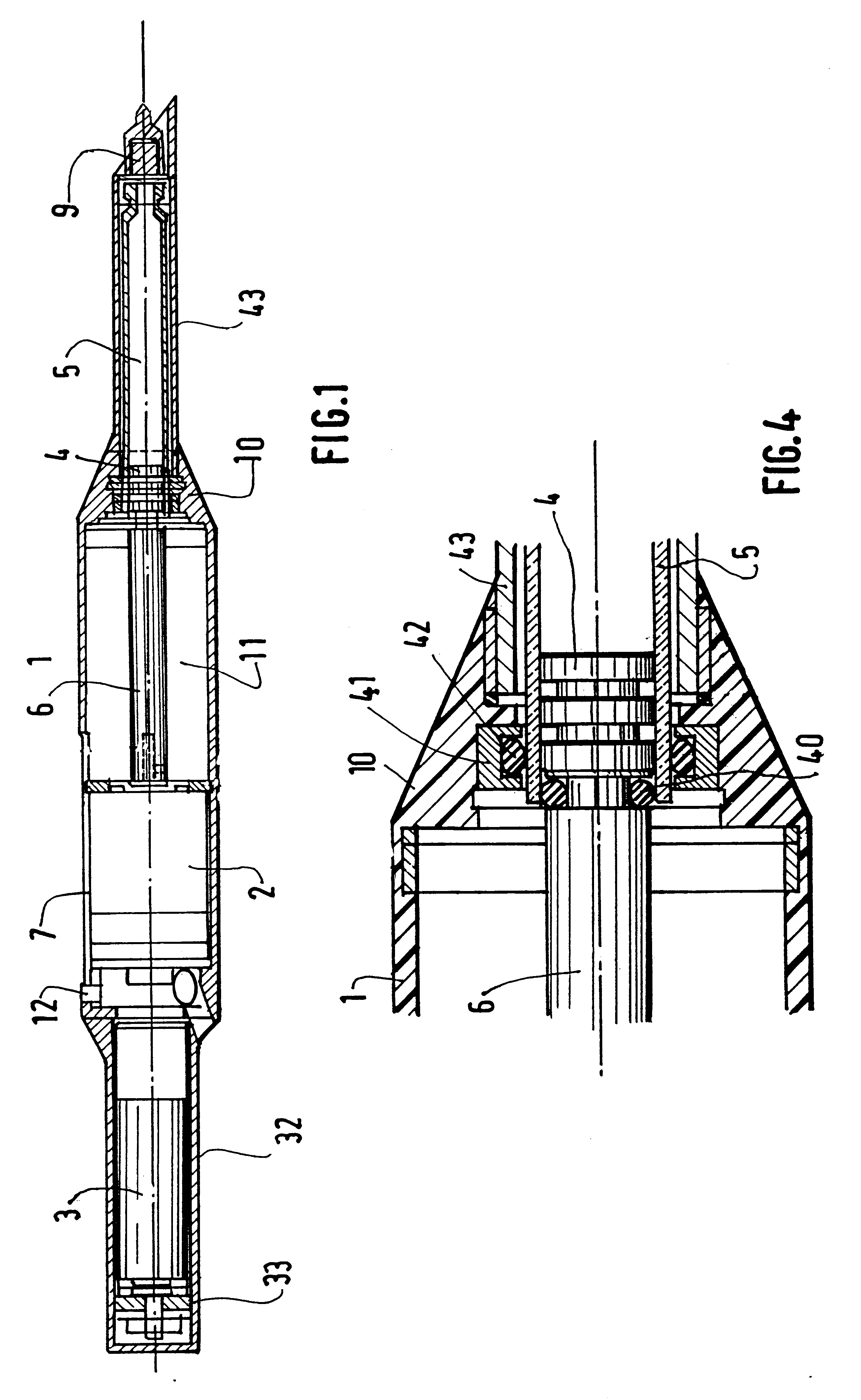
FIG. 1 shows an injector for dental anesthesia of the intradiploic type, i.e. requiring the needle to penetrate into a bone prior to injection. Under such circumstances, in addition to providing a motor for axial displacement or translation that serves to inject the anesthetic, it is also necessary to provide an additional motor capable of imparting rotary motion to the needle so as to facilitate passing through the bone prior to performing injection proper.

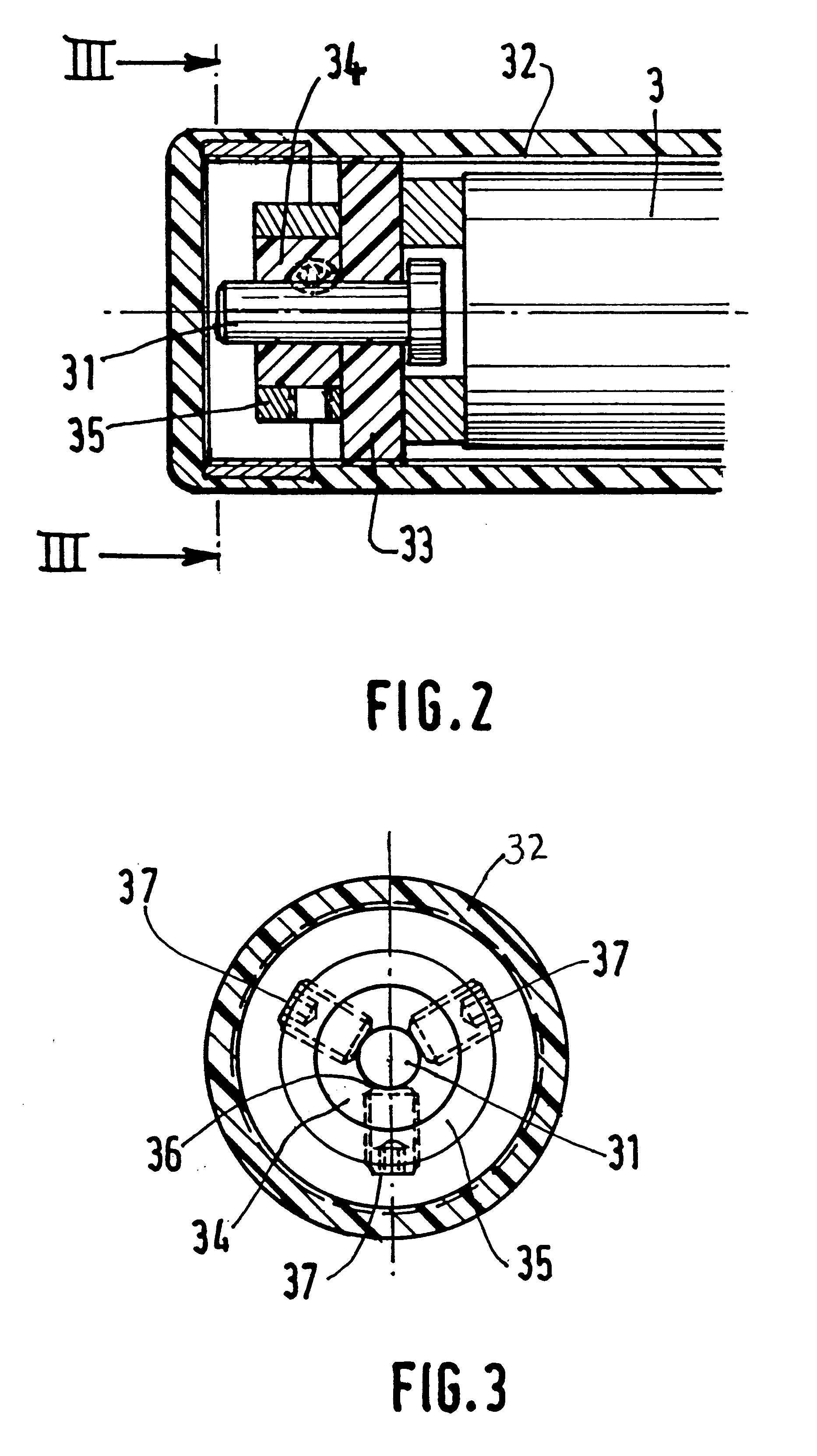
In FIG. 1, there can be seen a hollow cylindrical body 1 containing a motor 2 for rotating the cartridge and the needle 9, and a motor 3 for moving the motor 2 in axial displacement, and also a piston 6 whose front end bears against the sliding end wall 4 of the cartridge 5. A partially frustoconical housing 10 is mounted on the front of the body 1 to hold and guide the cartridge 5.

In accordance with the invention, the rotation motor 2 lies on the same axis as the injection motor 3, as the cartridge 5 (or supply of anesthetic), a...


PUM


Abstract

An injector for medical use, in particular with semisolid substances, the injector comprising a case and at least one injection electric motor pressing against a piston acting on the moving end of a cartridge, the motor being movable in translation inside the body in order to exert force on the axis.

Description

The present invention relates to an injector for use in dentistry, for performing intramedullary or intradiploic injections of anesthetic or for performing injections into soft tissue.In dental surgery, the conventional solution is to use a syringe to inject a determined quantity of liquid anesthetic into the gum of the patient at a certain distance from the tooth that is to be attended to. However, that procedure suffers from drawbacks such as a considerable latency time between injection and anesthetic action, and of a quantity of anesthetic being injected that is larger than necessary. To remedy those drawbacks, proposals have already been made to provide intradiploic anesthesia whereby injection takes place directly into the marrow of the maxillary bone after passing through the cortical substance. The action of the anesthetic is thus more effective. To this effect, it is known to cause the injection needle to rotate so as to facilitate penetration of the needle through the cort...

Claims


Application Information

Patent Timeline
IPC IPC(8): A61M5/20A61M5/32A61M5/31
CPCA61M5/20A61M2005/3112A61M2005/3289A61M2005/31588
Inventor VILLETTE, ALAIN
Owner VILLETTE ALAIN
Why Eureka
Try Eureka