Image recording device having a ground connector

a ground connector and image recording technology, applied in the field of image recording devices, can solve the problems of fatigue of printed circuitry and the substrate that supports it, and achieve the effect of reducing the generation of electromagnetic waves and increasing the size of the devi

Inactive Publication Date: 2001-06-19
MINOLTA CO LTD
View PDF6 Cites 13 Cited by
  • Summary
  • Abstract
  • Description
  • Claims
  • Application Information

AI Technical Summary

Benefits of technology

Using said construction, in an image recording device in which the camera body and the taking lens unit are electrically connected by means of a flexible circuit board, the camera body and taking lens unit are electrically connected by means of slidingly connected conductive members, as a result of which the grounding line may be strengthened without increasing the size of the device, and, e.g., the generation of electromagnetic waves may be reduced.

Problems solved by technology

However, in said conventional device, when the taking lens unit is made to rotate relative to the camera body, because both ends of the flexible circuit board are fixed to the other circuit boards, the area of the flexible circuit board near the rotatable connecting unit becomes twisted, so that the flat flexible circuit board becomes pulled along its lengthwise edges while the center part becomes compressed, which causes the printed circuitry and the substrate that supports it to become fatigued over time.

Method used


Image

  • Image recording device having a ground connector
  • Image recording device having a ground connector
  • Image recording device having a ground connector

Examples


Embodiment Construction

One embodiment of the present invention will be explained below with reference to the drawings.

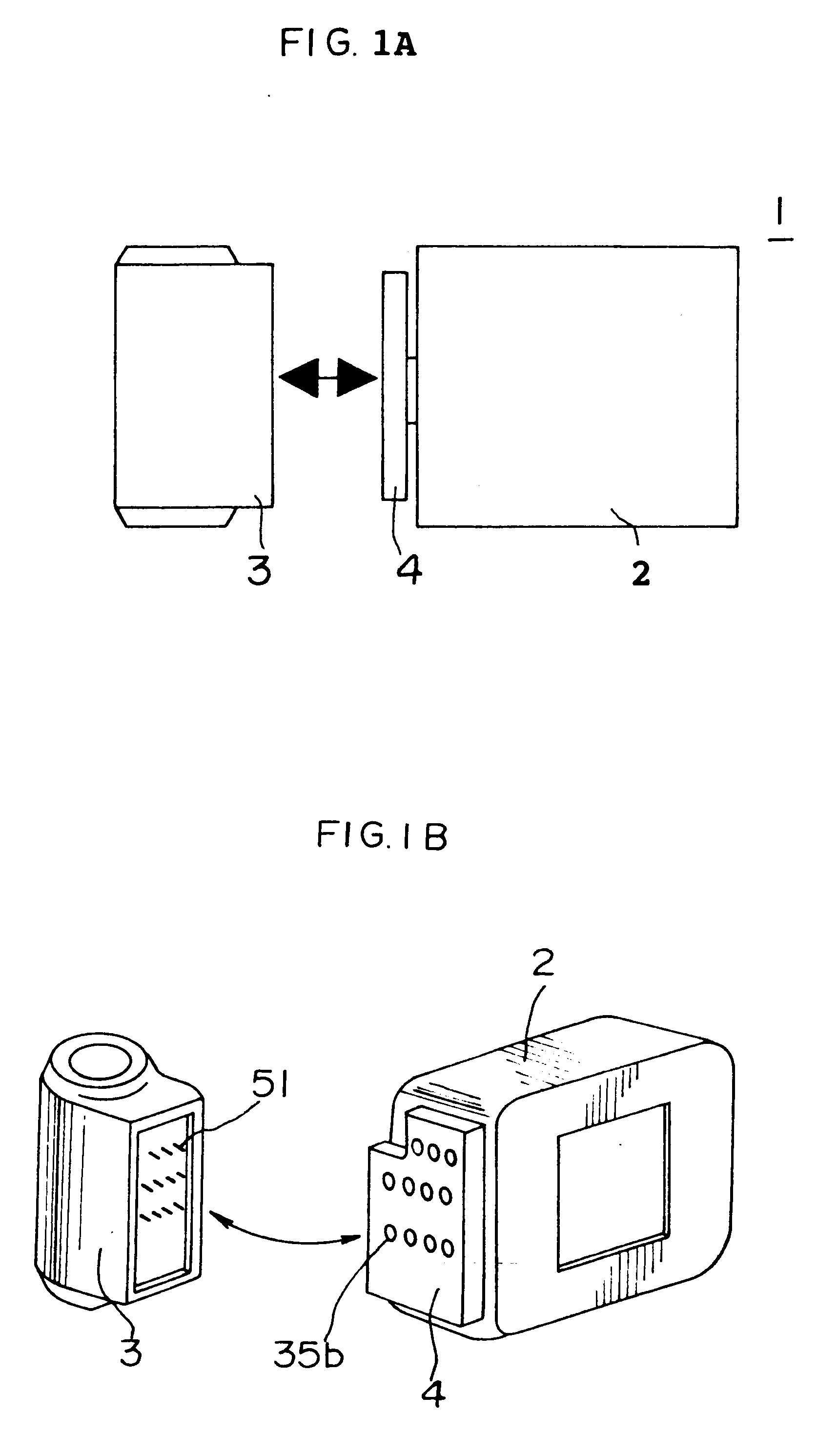
FIGS. 1A and 1B are drawings showing the construction of one embodiment of the present invention.

Digital camera 1 is equipped with a camera body 2 and a taking lens unit 3 detachably mounted to the camera body 2. A connector 4 constructed in a rotatable fashion is placed on a side of the camera body 2, and the taking lens unit 3 is rotatably mounted to the camera body 2 by means of its being attached to the connector 4. Multiple openings 35b are formed in the connector 4, and electric connectors are located in these openings. On the other hand, connecting pins 51 are located at positions on the taking lens unit 3 corresponding to the openings 35b. When the taking lens unit 3 is attached to the connector 4, connecting pins 51 penetrate the openings 35b and come into contact with the electrical connectors.

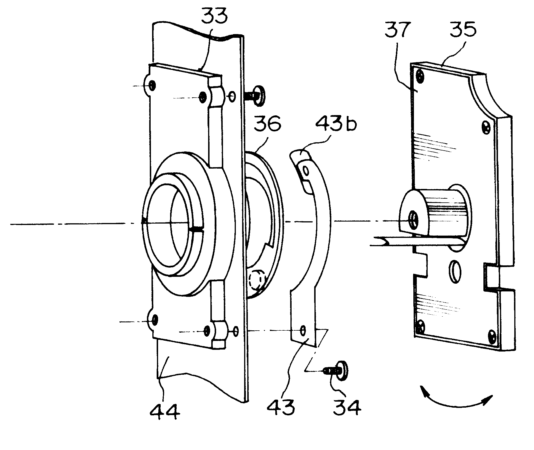
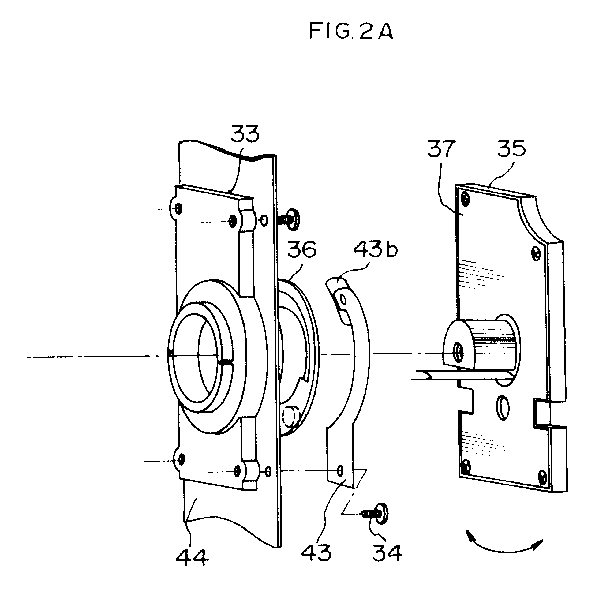
FIGS. 2A and 2B are exploded perspective views showing the details of the construction ...


PUM


Abstract

Camera body and taking lens unit are constructed such that they may rotate relative to each other, and circuit board of connector to which taking lens unit is mounted and the electrical circuitry inside the camera body are connected by means of flexible circuit board. Further, the grounding line is strengthened by having reinforcing plate that is in electrical contact with detachable circuit board comprise a metal plate and by having metal plate connected with the grounding line of the camera body to move against reinforcing plate.

Description

This application is based on application No. Hei 9-71659 filed in Japan, the content of which is hereby incorporated by reference.BACKGROUND OF THE INVENTION1. Field of the InventionThe present invention pertains to an image recording device in which a taking lens unit is rotatably supported by a camera body.2. Description of the Prior ArtConventionally, in this type of image recording device, in order to make the camera body and taking lens unit rotatable relative to each other, the two are normally connected electrically by means of a flexible circuit board. In other words, the flexible circuit board is placed in a linking space formed along the rotational axis inside the rotatable connecting unit connecting the camera body and the taking lens unit, and the ends of the flexible circuit board are fixed and electrically connected to circuit board fixed inside the camera body and taking lens unit, respectively.However, in said conventional device, when the taking lens unit is made to...

Claims


Application Information

Patent Timeline
Patent Type & Authority Patents(United States)
IPC IPC(8): G03B17/02G03B17/14
CPCG03B17/02H04N5/2251H04N5/772H04N23/50
Inventor ITOH, HISANORIITOH, MASATOSHISUGITA, MITSUHIRO
Owner MINOLTA CO LTD
Why Eureka
Try Eureka