
Living body determination device, living body determination method, and program

a technology of living body and determination method, applied in the direction of optical radiation measurement, diagnostics using spectroscopy, instruments, etc., can solve the problem of insufficient achieve accurate determination of living bodies, improve the reliability of biometric authentication, and increase the size of the device

Active Publication Date: 2018-08-23
NEC CORP
View PDF0 Cites 3 Cited by
  • Summary
  • Abstract
  • Description
  • Claims
  • Application Information

AI Technical Summary

Benefits of technology

The invention aims to provide a device, method, and program for accurately determining if a living body is present without adding size or complexity. Additionally, it can detect forged fingerprint fragments. The invention also seeks to improve the reliability and security of biometric authentication.

Problems solved by technology

However, reliability of biometric authentication was not sufficiently high because there were some cases where a forged physical characteristic (for example, a false finger) was erroneously determined as genuine.

Method used


Image

  • Living body determination device, living body determination method, and program
  • Living body determination device, living body determination method, and program
  • Living body determination device, living body determination method, and program

Examples


first exemplary embodiment

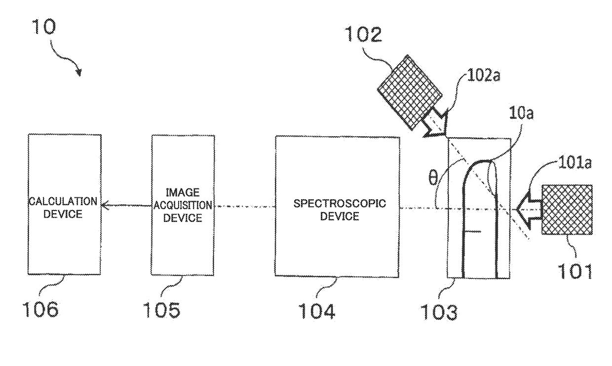
[0087]FIG. 1 is a block diagram showing a configuration of a living body determination device according to a first exemplary embodiment of the present invention.

[0088]Referring to FIG. 1, a living body determination device 10 has light emission devices 101, 102, a measurement target placement device 103, a spectroscopic device 104, an image acquisition device 105, and a calculation device 106.

[0089]The measurement target placement device 103 includes a pedestal for placing a measurement target 10a. Here, the measurement target 10a is a part of a body (for example, a finger or a hand). In FIG. 1, a finger is schematically shown as an example of the measurement target 10a.

[0090]The light emission devices 101, 102 emit lights 101a, 102a from mutually different directions toward the pedestal of the measurement target placement device 103. The light emission device 101 is disposed at a position facing the spectroscopic device 104 with the pedestal therebetween. In the case where the ped...

first application example

Device

[0145]Next, a biometric authentication device to which the living body determination device of the first exemplary embodiment described above is applied will be described.

[0146]The biometric authentication device of the present example is such that the calculation device 106 of the living body determination device 10 shown in FIG. 1 is replaced with a calculation device 106a having a biometric authentication function. The configuration other than the calculation device 106a is basically the same as that of the living body determination device 10.

[0147]FIG. 12 is a block diagram showing the configuration of the calculation device 106a.

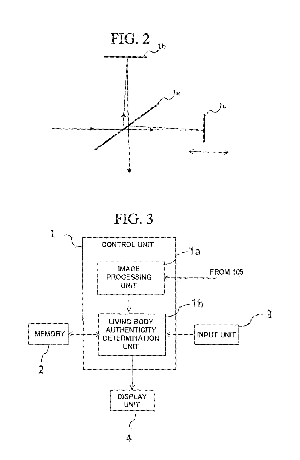
[0148]Referring to FIG. 12, the calculation device 106a has a control unit 11, a memory 12, an input unit 13, and a display unit 14. The input unit 13 and the display unit 14 are the same as the input unit 3 and the display unit 4 shown in FIG. 3.

[0149]The memory 12 is similar to the memory 2 shown in FIG. 3, and stores a program and data (includ...

second exemplary embodiment

[0176]A living body determination device according to a second exemplary embodiment of the present invention has a configuration similar to that of the first exemplary embodiment. However, it differs from the first exemplary embodiment in that it uses brightness change information C indicating temporal changes in brightness in addition to spectroscopic image information A, B. Here, the configuration that differs from that of the first exemplary embodiment will be mainly described, and a description of the same configuration will be omitted.

[0177]In the period p shown in FIG. 4A or FIG. 4B, the image processing unit 1a turns on the light emission device 101 and turns off the light emission device 102. The image processing unit 1a acquires a plurality of pieces of image information I1 related to the measurement target 10a from the image acquisition device 105, and calculates the spectroscopic image information A and brightness change information C.

[0178]In the period q shown in FIG. 4...


PUM


Abstract

A living body is accurately determined while minimizing increases in the size of a device and increases in the number of components. A living body determination device includes a spectroscopic device 104 that disperses light entering from a pedestal side and outputs the result; a light emission device 101 that emits first light toward the pedestal from a position facing the spectroscopic device 104 with the pedestal therebetween; a light emission device 102 that emits second light toward the pedestal from the spectroscopic device 104 side; an image acquisition device 105 that outputs image information indicating a brightness corresponding to the intensity of the light output by the spectroscopic device 104; and a calculation device 106 that acquires first image information regarding each of the spectra of the first light from the image acquisition device 105, acquires first spectroscopic information on the basis of each of the pieces of first image information, acquires second image information regarding each of the spectra of the second light from the image acquisition device 105, acquires second spectroscopic information on the basis of each of the pieces of second image information, and determines whether or not a measurement target 10a is a living body, based on the first and second spectroscopic information.

Description

TECHNICAL FIELD[0001]The present invention relates to a living body determination device, a living body determination method, and a program for determining whether or not a measurement target is a living body. The present invention also relates to a biometric authentication device, a biometric authentication method, and a program to which such living body determination is applied.BACKGROUND ART[0002]In recent years, there have been provided various devices and systems having a biometric authentication function for performing biometric authentication with use of biometric information indicating physical features such as fingerprints. However, reliability of biometric authentication was not sufficiently high because there were some cases where a forged physical characteristic (for example, a false finger) was erroneously determined as genuine.[0003]Therefore, as a countermeasure against fraudulent authentication using a false finger or the like, living body determination is being perf...

Claims


Application Information

Patent Timeline
Patent Type & Authority Applications(United States)
IPC IPC(8): G06K9/00A61B5/1172A61B5/00G01J3/447G01J3/28G06V10/143
CPCG06K9/0012A61B5/1172A61B5/0075G06K9/00087G01J3/447G01J3/2823A61B5/489G01J3/4535G01J3/42G06V40/1312G06V40/1394G06V10/143G06V40/1365
Inventor OHNO, YUJIKUBO, MASAHIROABE, KATSUMITAKOH, KIMIYASUALTINTAS, ERSINAKAGAWA, TAKESHIARIYAMA, TETSURIISHIMARU, ICHIRO
Owner NEC CORP
Learn More