Drive method for plasma display panel

a drive method and plasma display technology, applied in the direction of instruments, static indicating devices, etc., can solve the problems of insufficient sustain pulse voltage applied between the scan electrode and the sustain electrode, the inability to sustain the discharge and eventually stop,

Inactive Publication Date: 2001-06-26
PIONEER CORP
View PDF13 Cites 46 Cited by
  • Summary
  • Abstract
  • Description
  • Claims
  • Application Information

AI Technical Summary

Problems solved by technology

Even if the above-described pulse voltage maintains a uniform value, discharge cannot be sustained and eventually stops.
As a result, the amplitude of sustain pulses must be lower than the initial discharge voltage between opposite electrodes, resulting in cases of insufficient sustain pulse voltage applied between the scan electrodes and sustain electrodes.
At substantially the same time, the superimposed voltage between the positive-polarity 1 / 2 sustaining discharge pulse applied to the scan electrode and the positive wall charge on the scan electrode and the negative wall charge on the data electrode occurs discharge between opposite electrodes, thereby resulting in instability of sustaining discharge between the scan electrode and sustain electrode.
In such cells, the amount of charge is low at the time of applying a leading sustain pulse, and the leading sustaining discharge is therefore weak.
If discharge between opposite electrodes occurs at the same time, the amount of charge that contributes to surface discharge is even further diminished, sufficient wall charge does not form on the scan electrode and sustain electrode in the leading sustaining discharge, and second and subsequent sustaining discharges are difficult to continue.

Method used


Image

  • Drive method for plasma display panel
  • Drive method for plasma display panel
  • Drive method for plasma display panel

Examples


first embodiment

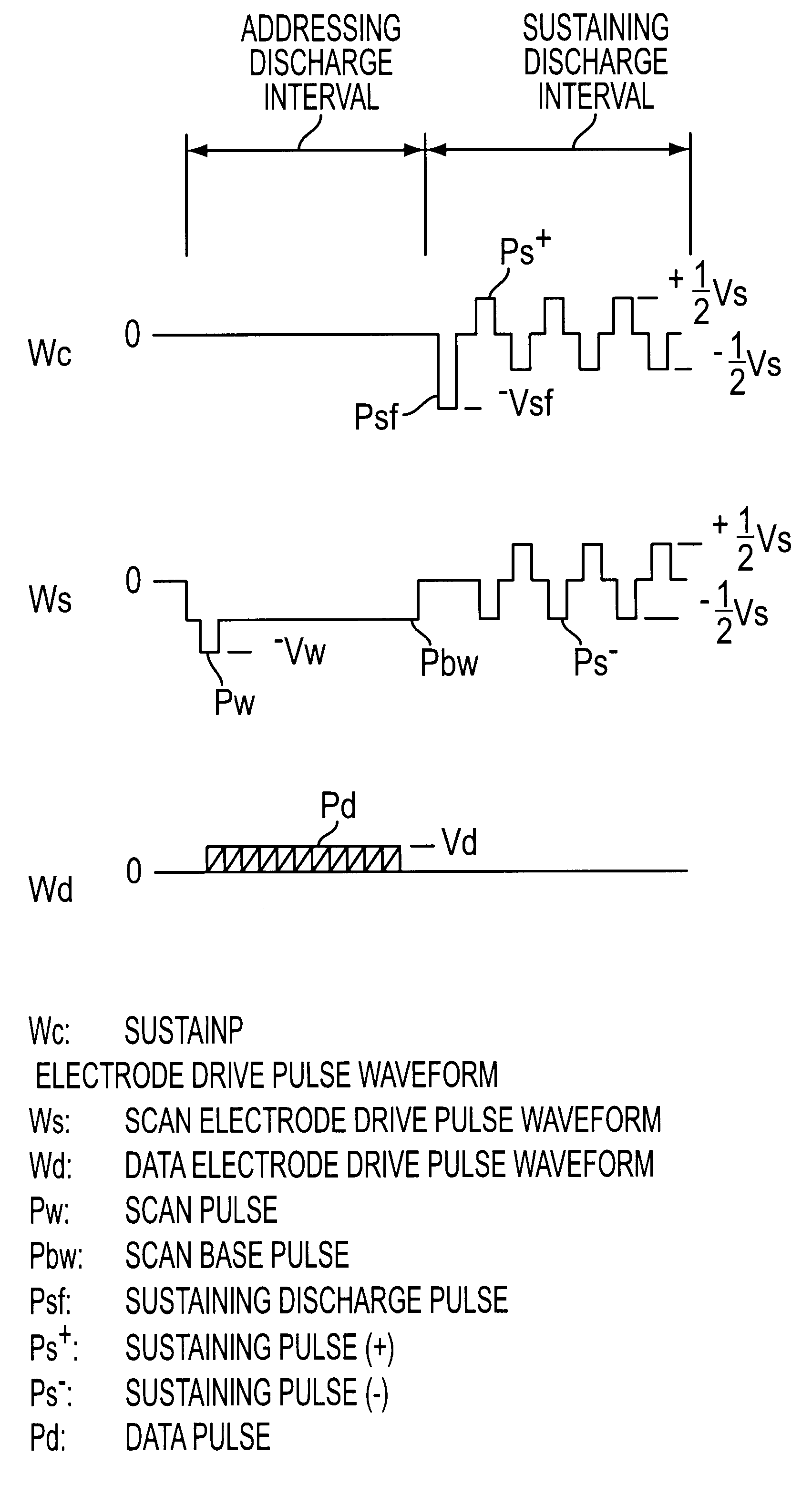
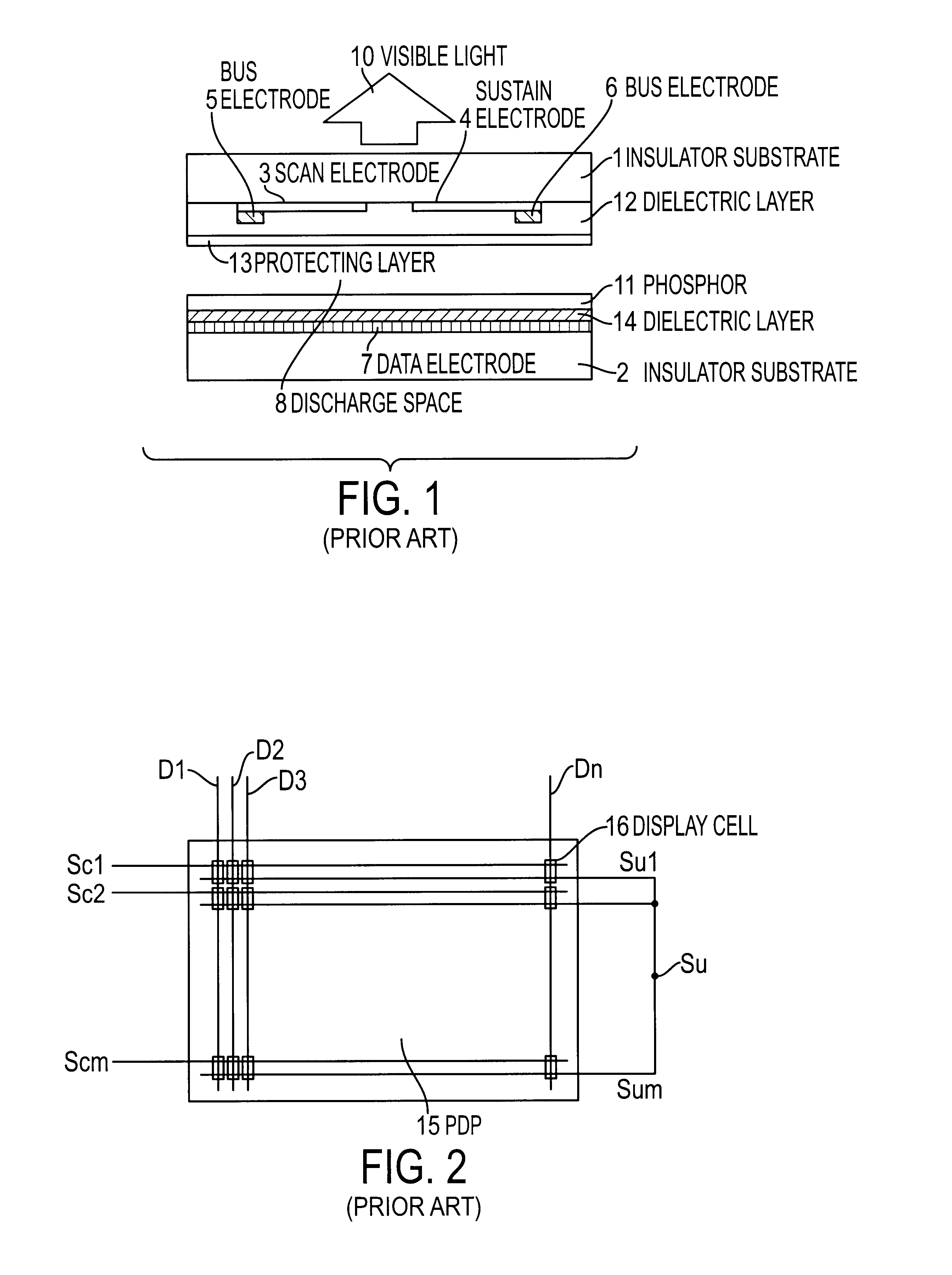
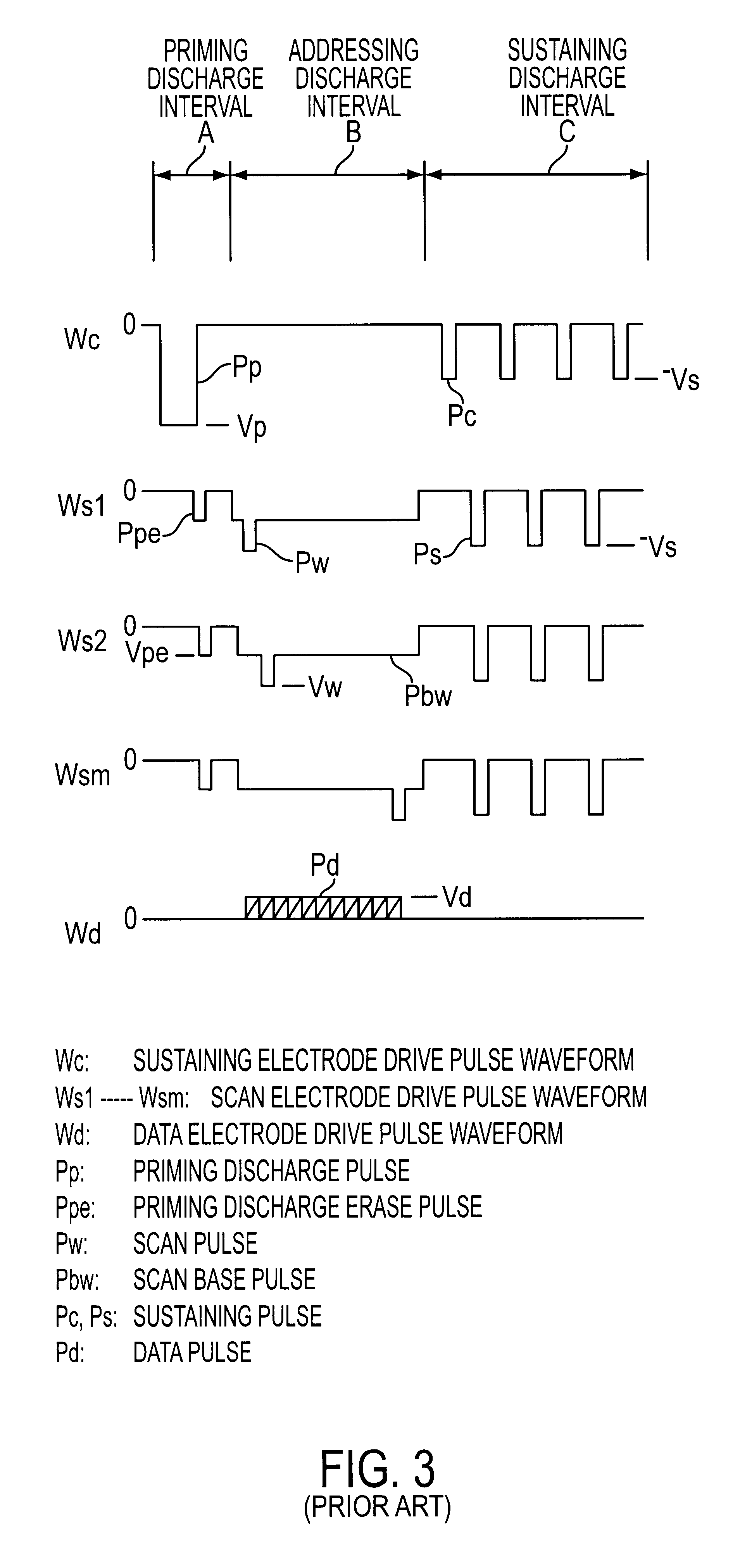
FIG. 6 is a drive waveform chart of the PDP according to the present invention. The electrode structure of the panel is the same as that of the prior art, and explanation is therefore presented using FIG. 2. Wc is the sustain electrode drive waveform applied in common to sustain electrodes Su1, Su2, . . . , Sum; Ws1, Ws2, . . . , Wsm are scan electrode drive waveforms applied to scan electrodes Sc1, Sc2, . . . , Scm, respectively; and Wd is the data electrode drive waveform applied to data electrode Di (1.ltoreq.i.ltoreq.n). One period (one frame) of drive is composed of priming discharge interval A, addressing discharge interval B, and sustaining discharge interval C; and the desired image display is obtained by he repetition of these intervals.

Priming discharge interval A is a period for generating wall charge and active particles in the discharge space so as to obtain stabilized addressing discharge characteristics in addressing discharge interval B. First, positive-polarity prim...

second embodiment

FIG. 9 shows drive waveforms of a PDP according to the present invention. The panel electrode configuration is the same as that of the prior art, and explanation is therefore presented using FIG. 2. Wc is the sustain electrode drive waveform applied in common to sustain electrodes Su1, Su2, . . . , Sum; Ws1, Ws2, . . . , Wsm are the scan electrode drive waveforms applied to each of scan electrodes Sc1, Sc2, . . . , Scm, respectively; and Wd is the data electrode drive waveform applied to data electrode Di (1.ltoreq.i.ltoreq.n). One period of drive (one frame) is composed of priming discharge interval A, addressing discharge interval B, and sustaining discharge interval C; and the desired image display is obtained by repetition of these intervals.

FIG. 10 shows sectional views of the state of the wall charge at the time of applying each pulse in a display cell of the PDP according to the second embodiment of the present invention.

Priming discharge interval A and addressing discharge i...


PUM


Abstract

In a conventional plasma display panel drive method, making the sustaining discharge pulse bipolar with respect to the data electrode potential prevents stable discharge in the leading sustaining discharge pulse, thereby complicating continuation to second and subsequent sustaining discharges. The plasma display panel drive method of this invention makes the potential of the leading sustaining discharge pulse a negative polarity to the data electrode potential, and moreover, makes the high-potential side of second and subsequent sustaining discharge pulses positive polarity to the data electrode potential, and makes the low-potential side negative polarity with respect to the data electrode potential.

Description

1. Field of the InventionThe present invention relates to a drive method for a plasma display panel, and particularly to a drive method for an AC memory type plasma display panel.2. Description of the Related ArtPlasma display panels (hereinbelow abbreviated "PDP") typically offer many features including thin construction, freedom from flicker, and a high display contrast ratio, and in addition are relatively easy to apply to large screens. They have a high response speed, and are the emissive type which can display color images using a phosphor. As a result, PDP are becoming increasingly widely used in recent years in the fields of computer-related display devices and color image display devices.Depending on the method of operation, plasma display panels can be divided between the AC type, in which electrodes are covered by a dielectric and which are operated indirectly by AC discharge, and the DC type, in which the electrodes are exposed in a discharge space and which are operated...

Claims


Application Information

Patent Timeline
Patent Type & Authority Patents(United States)
IPC IPC(8): G09G3/28G09G3/288G09G3/20G09G3/291G09G3/294
CPCG09G3/294G09G3/2927G09G2320/0228
Inventor ISEKI, KOKINAKAMURA, TADASHI
Owner PIONEER CORP
Why Eureka
Try Eureka