Engineered wood products cutting method and apparatus

a cutting method and wood technology, applied in the direction of metal sawing accessories, manufacturing tools, instruments, etc., can solve the problems of inconvenient handling of ewp members, difficulty in accurate length measurement by a conventional measuring wheel assembly, and inconvenient addition of length of ewp members

Inactive Publication Date: 2001-07-24
ILLINOIS TOOL WORKS INC
View PDF9 Cites 71 Cited by
  • Summary
  • Abstract
  • Description
  • Claims
  • Application Information

AI Technical Summary

Benefits of technology

Numeral references are employed to designate like parts throughout the various figures of the drawing. Terms such as "left," "right," "clockwise," "counter-clockwise," "horizontal," "vertical," "up" and "down," "forward" and "backward" when used in reference to the drawings, generally refer to orientation of the parts in the illus

Problems solved by technology

Unfortunately, the added length of the EWP members is inconvenient to handle when cutting to size for a production site.
The added length makes accurate length measurement by a conventional measuring wheel assembly difficult and slows production when using a push-foot type feeder system.
While small inaccuracies in length measurement may not cause a significant variance when measuring a shorter conventional wood member, the cumulative effect of such measurement inaccuracies over the length of the longer EWP members may result in unacceptable length variances.
One type of error in measuring the length of an EWP member can be caused from measuring an EWP which is bent, bowed or otherwise misshapen.
Inaccuracies in measurement by a wheel measurement assembly may be caused by imperfections in the wood and by the type of measur

Method used


Image

  • Engineered wood products cutting method and apparatus
  • Engineered wood products cutting method and apparatus
  • Engineered wood products cutting method and apparatus

Examples


Embodiment Construction

The invention is herein described with reference to the accompanying drawings and is not intended to limit the scope of the claimed invention, but is intended to describe particular embodiments to disclose the best mode of the invention to those skilled in the art

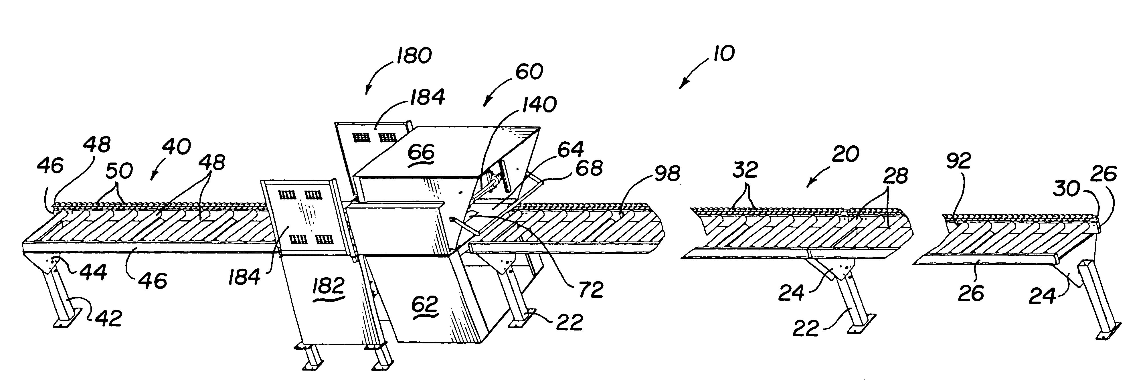
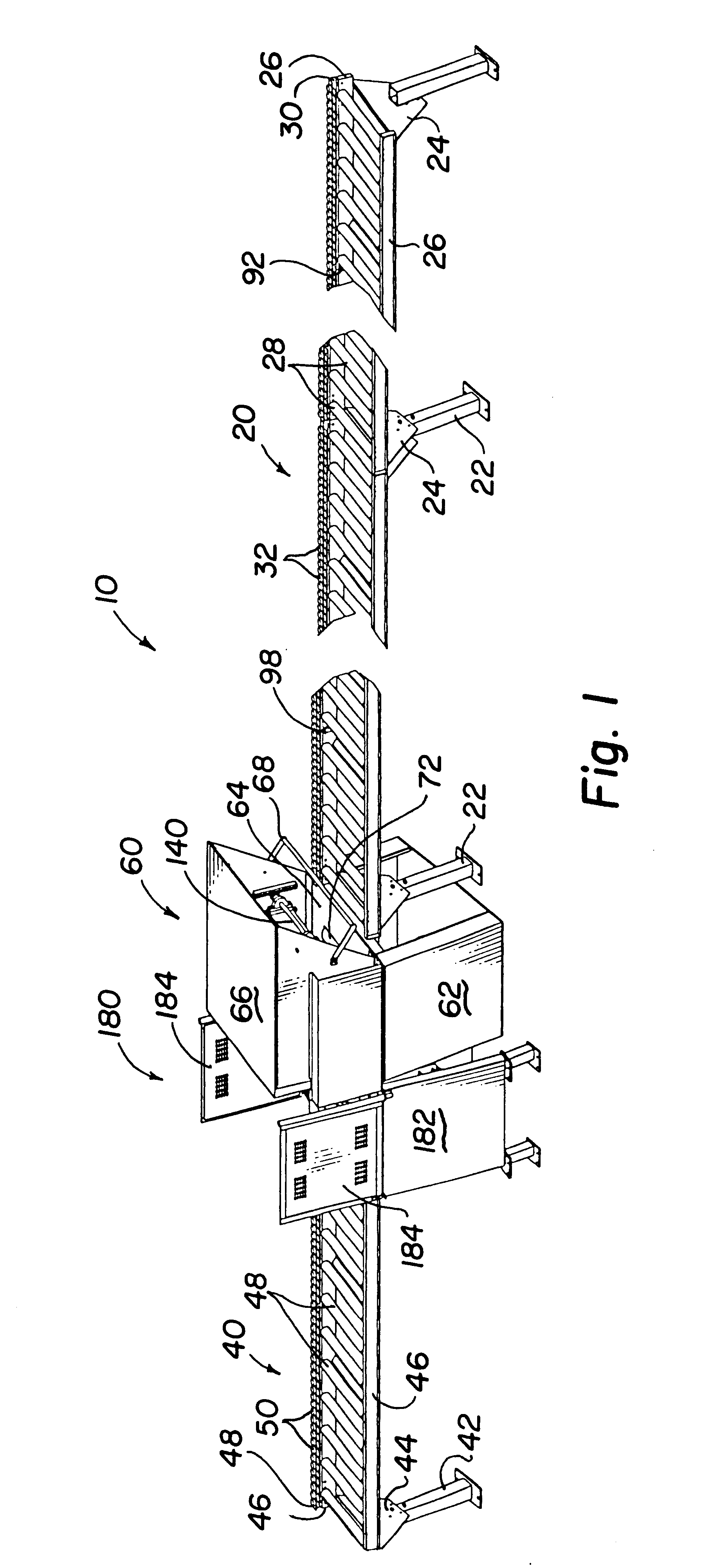
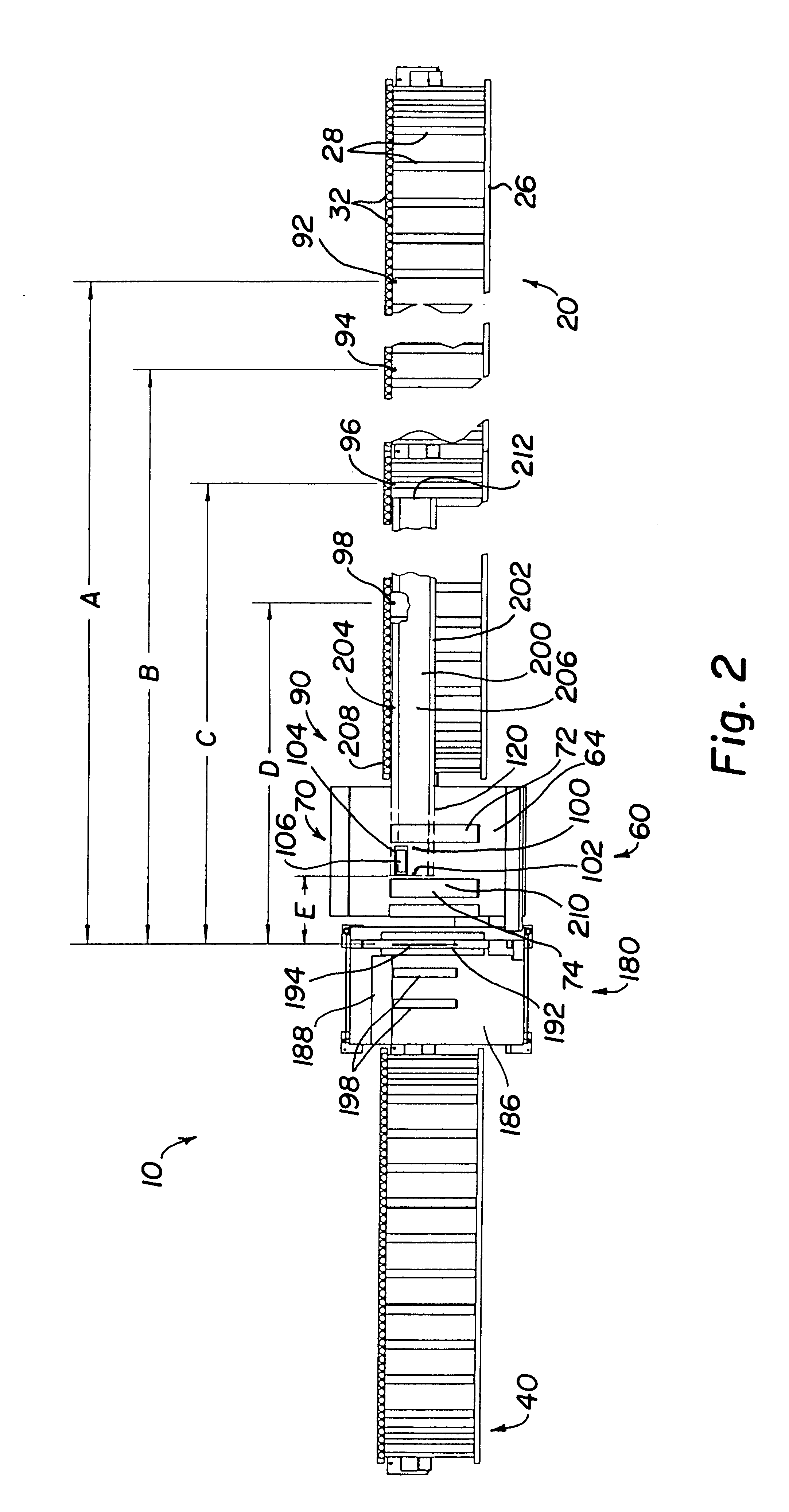
FIGS. 1 and 2 show an engineered wood product (EWP) processing apparatus 10 having an infeed table 20, an outfeed table 40, a driving unit 60 and a cutting unit 180. The infeed and outfeed tables have legs 22 and 42, support brackets 24 and 44, and side rails 26 and 46 supporting a plurality of feed rollers 28 and 48, all respectively. The support brackets are preferably designed such that the feed rollers are supported at an angle with respect to the floor surface (as best seen in FIG. 8). The infeed table 20 has a lower side rail 26 which preferably supports a stop rail 30 having a plurality of stop rail rollers 32. Similarly, the outfeed table 40 preferably comprises a stop rail 50 with a plurality of stop rail rollers 5...


PUM

PropertyMeasurementUnit
Diameteraaaaaaaaaa
Lengthaaaaaaaaaa
Pressureaaaaaaaaaa

Abstract

The invention is a method and apparatus for processing an Engine Wood Product member. The member is moved to a home position in a driving unit and the length of the EWP member is automatically measured by moving the EWP member from the home position while engaging the EWP member with a measuring assembly including a measuring wheel having a smooth hard facing, the facing contacting the EWP member. The member is moved to a first cutting position and cut to a predetermined length. Activating one or more position sensor devices, at least one of the position sensor devices positioned such that the EWP member engages the position sensor device while the member is in the home position, the length of the member is determined as it is moved from the home position. Moving the EWP member is accomplished by clamping the EWP member between at least one driver roller and at least one pressure roller, each driver roller aligned with a corresponding pressure roller, and rotating the at least one driver roller to move the EWP member. First and second driver rollers may be spaced apart and positioned on opposite sides of the measuring wheel. An outfeed table and infeed table with angled rollers may further be employed.

Description

The present invention relates to a method and apparatus for the automatic measuring and cutting of engineered wood products.BACKGROUND OF INVENTIONThe construction industry has seen an increase in the use of engineered wood products (EWP) in building projects. EWP members differ from conventional wood products in that EWP members are fiber-glue composites. I-beam type EWP members typically have flange members of solid cut wood and web members of composite wood. EWP members also include rectangular beams formed of lumber strips or veneers glued together. These products are known as glue laminated beams, laminated veneer lumber (LVL), or Microlam.RTM. Parallam.RTM., laminated strand lumber (LSL), and by other names. EWP members are differentiated in the art from panel type products such as plywood, oriented strand board (OSB), particle board and the like. The EWP can be manufactured to any length, offering an advantage over normal wood members which are limited in length by the size o...

Claims


Application Information

Patent Timeline
IPC IPC(8): B23D59/00B27B31/00
CPCB27B31/003B23D59/001Y10T83/04Y10T83/148Y10T83/54Y10T83/541Y10T83/155
Inventor MCADOO, DAVID L.BLAINE, GEORGE
Owner ILLINOIS TOOL WORKS INC
Why Eureka
Try Eureka