Chaos applied apparatus

a technology of apparatus and chaos, which is applied in the field of chaos applied apparatus, can solve the problem of not achieving sufficient washing

Inactive Publication Date: 2001-07-24
PANASONIC CORP
View PDF9 Cites 37 Cited by
  • Summary
  • Abstract
  • Description
  • Claims
  • Application Information

AI Technical Summary

Benefits of technology

To achieve the object, the invention presents a rotary nozzle apparatus comprising a pump for pressurizing a fluid, a nozzle composed of plural rotatable hollow links which are mutually in passing through, and at least one fluid injection port in at least one hollow link of the nozzle, in which the fluid is injected from the injection port while rotating the hollow link by the force of the fluid pressurized by the pump, and the shape, weight, and position of center of gravity of the link, the fluid injection angle of the injection port, and the pressurizing pattern of the pump are adjusted, so that the motion of the nozzle is set in chaotic state.

Problems solved by technology

Therefore, the water injected from the rotary nozzle 1050 hits only a limited area of a dish, and sufficient washing effect is not obtained depending on the configuration of dishes, or water does not permeate into narrow gaps of dishes.

Method used


Image

  • Chaos applied apparatus
  • Chaos applied apparatus
  • Chaos applied apparatus

Examples


first embodiment

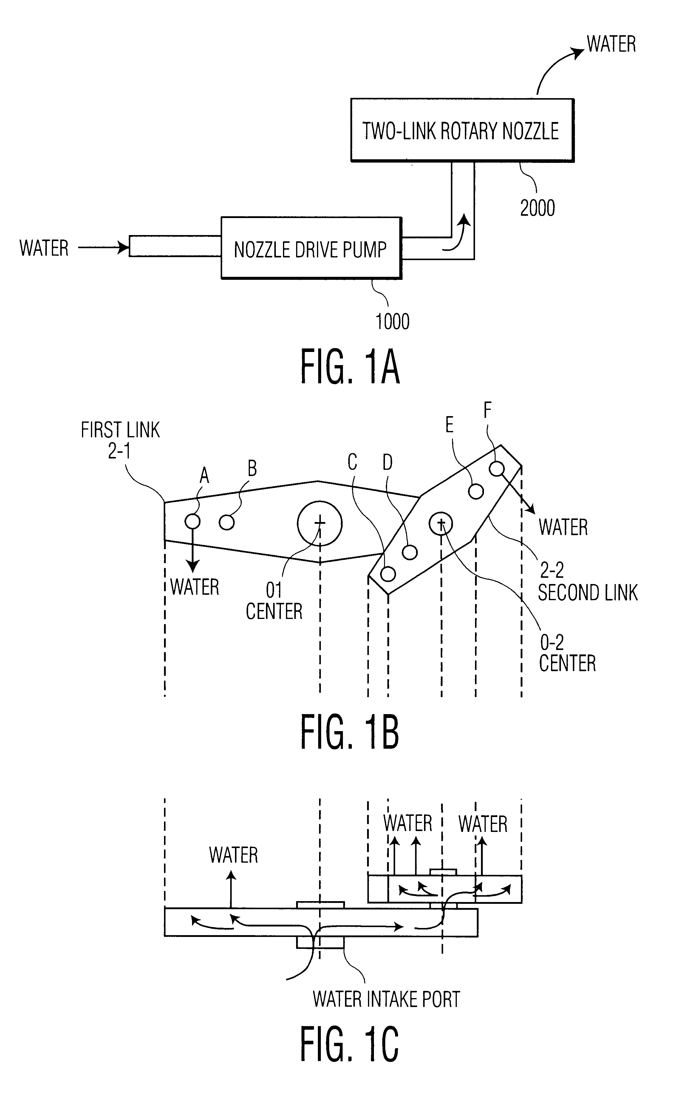
FIG. 1 (a) is a structural diagram of a rotary nozzle apparatus in the invention. Reference numeral 1000 denotes a nozzle drive pump for pressurizing feed water, and 2000 is a two-link rotary nozzle which is rotated by the force of water pressurized by the nozzle drive pump 1000 so as to inject water.

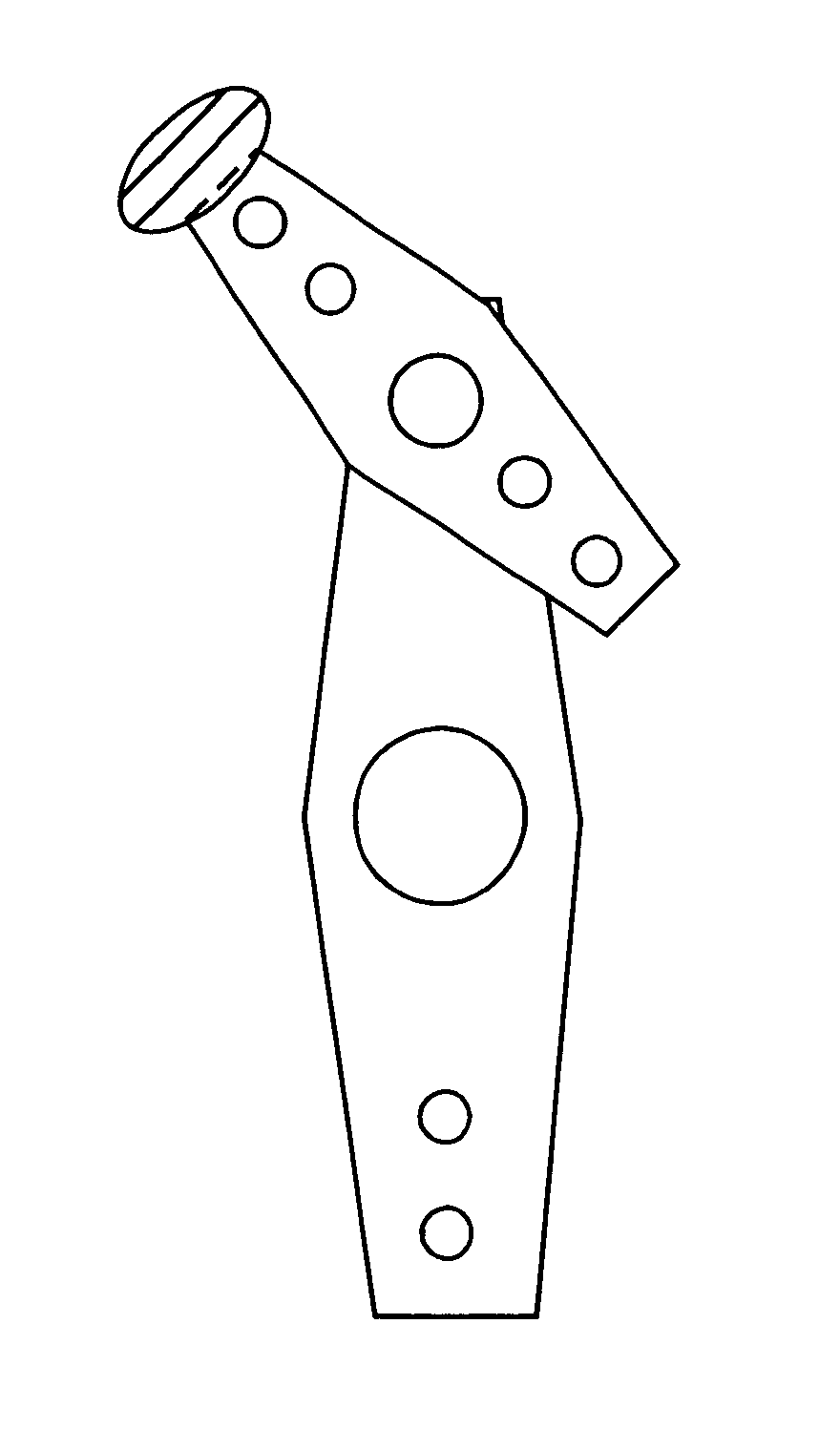
A detailed structure of the two-link rotary nozzle 2000 is shown in FIG. 1 (b). The upper half of FIG. 1 (b) is a top view of the two-link rotary nozzle 2000, and the lower half is a side view. As shown in FIG. 1 (b), the two-link rotary nozzle 2000 is composed of two links (first link 2-1, second link 2-2). Each link has plural injection ports, which are expressed by symbols A to F in FIG. 1 (b). The direction of blowing water from each injection port differs in each injection port.

The links and link connection parts are hollow, and the water coming supplied up to the water intake port beneath the first link passes through the inside of the hollow link, and can reach up to the injectio...

second embodiment

A chaotic state is more likely to occur when the degree of freedom of the object system is higher. In the second embodiment, by varying the output of the nozzle drive pump 1000, the degree of freedom of the entire nozzle drive device is increased, and a chaotic state is produced. In other method of increasing the degree of freedom of the system, for example, the structure of the joint of each link can be changed.

In this embodiment, the link joint structure is modified, and the rotary nozzle apparatus is set in chaotic state as described below.

The structure of the joint part of the link of the rotary nozzle apparatus disclosed in the first embodiment is as shown in FIG. 9.

FIG. 9 (1) shows the structure of the joint of the first link 2-1 and second link 2-2 of the two-link rotary nozzle 2000 Usually, the second link 2-2 is put on the joint enclosed by a circle, and fixed with nut so that the second link 2-2 may not be separated from the first link 2-1. However, the second link 2-2 is ...

third embodiment

What differs from the third embodiment is the provision of a sensor 3000 for detecting the motion of the two-link rotary nozzle, and chaos feature amount calculating circuit for calculating the feature amount of chaos from the observation about the motion of the nozzle detected by the sensor 3000. In thus constituted rotary nozzle apparatus, the operation is described below.

The first to third embodiments relate to the nozzle drive device which operates in chaotic state. In a dish washer, for example, uniform injection of water is demanded, and it is desired to operate the nozzle always in chaotic state.

If, however, the nozzle is disturbed by dust etc., and the dynamic characteristic of the system varies, the chaotic state may not be always maintained in the methods explained in the first to third embodiments. To avoid such case, in this embodiment, the nozzle motion is detected in real time, and an apparatus capable of driving always in stable chaotic state is presented.

The sensor 3...


PUM


Abstract

A rotary nozzle device is described. The device includes plural rotatable hollow links which are mutually passable through, a pump for feeding a pressurized fluid into the hollow links, and at least one fluid injection port in at least one hollow link of the nozzle. Moreover, the fluid is injected from the injection port while the hollow link is rotated by the force of the fluid pressurized by the pump, and the motion of the injection port is set in chaotic state by adjusting a structural characteristic of the nozzle.

Description

1. Industrial Field of UtilizationThe present invention relates to an apparatus in which a chaos technology is applied.2. Related Art of the InventionThe prior art is described below while referring to an example of dish washer.A conventional dish washer is shown in FIG. 14. Reference numeral 1010 denotes a body of a dish washer, 1020 is a lid through which dishes are put inside the dish washer, 1030 is a feed water hose for feeding water into the dish washer, 1040 is a nozzle drive pump for pressurizing water from the feed water hose 1030, 1050 is a rotary nozzle, 1060 is a drain pump for discharging water collected inside, 1070 is a drain hose for leading wastewater to outside of the dish washer, and 1080 is a control circuit for controlling the operation timing of the nozzle drive pump 1040 and drain pump 1060. In thus constituted conventional dish washer, the water supplied from the feed water hose 1030 is pressurized by the nozzle drive pump 1040, and is supplied into the rotar...

Claims


Application Information

Patent Timeline
Patent Type & Authority Patents(United States)
IPC IPC(8): H05B6/68B05B12/00G05B13/00
CPCA47L15/23A47L15/46H05B6/66Y02B40/143A47L2501/04A47L2401/24Y02B40/00F24C7/00
Inventor NOMURA, HIROYOSHIWAKAMI, NOBORUAIHARA, KAZUYUKI
Owner PANASONIC CORP
Why Eureka
Try Eureka