Microstrip arrangement

a microstrip and arrangement technology, applied in the direction of stripline fed arrays, waveguides, high frequency circuit adaptations, etc., can solve the problems of non-dielectric properties of conductors, non-plane design drives up manufacturing costs,

Inactive Publication Date: 2001-07-24
HIGHBRIDGE PRINCIPAL STRATEGIES LLC AS COLLATERAL AGENT
View PDF11 Cites 228 Cited by
  • Summary
  • Abstract
  • Description
  • Claims
  • Application Information

AI Technical Summary

Problems solved by technology

In conventional circuit board technology, for reasons of cost, use is made of dielectric materials which for inter alia the abovementioned reason are not suitable as a dielectric in microstrip arrangements.
These inexpensive dielectric materials also have the disadvantage that their dielectric properties are not always the same at all points in one and the same circuit board.
As conventional microstrip technology often makes use of a conductor that is "buried" in the dielectric, access to the conductor is rendered difficult.
A further problem with dielectric materials in microstrip conductors may be material variations between different deliveries of one and the same dielectric material from one and the same manufacturer.
A disadvantage of this solution is that a non-plane design drives up the manufacturing cost.
Certain losses also occur in the electrically conductive material itself, compared with when the material is of plane design.
Another type of loss that may arise on account of the properties of the dielectric material is reflection losses, in other words losses at the point where the microstrip arrangement is connected to other equipment, in the case of an antenna especially transmitting or receiving equipment.
This arrangement is dependent for its function on being positioned in a longitudinal cavity formed in a solid metal piece, which would seem to have the effect of making the arrangement bulky as well as costly to manufacture.
The arrangement also requires the use of relatively expensive dielectric material, for example RT / DUROID 6010.RTM..

Method used


Image

  • Microstrip arrangement
  • Microstrip arrangement
  • Microstrip arrangement

Examples


Embodiment Construction

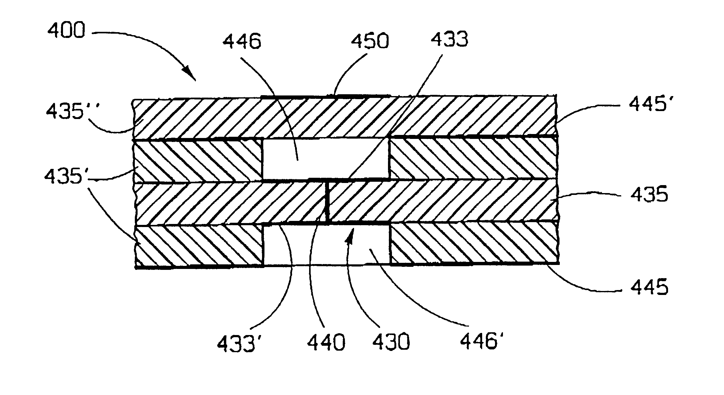
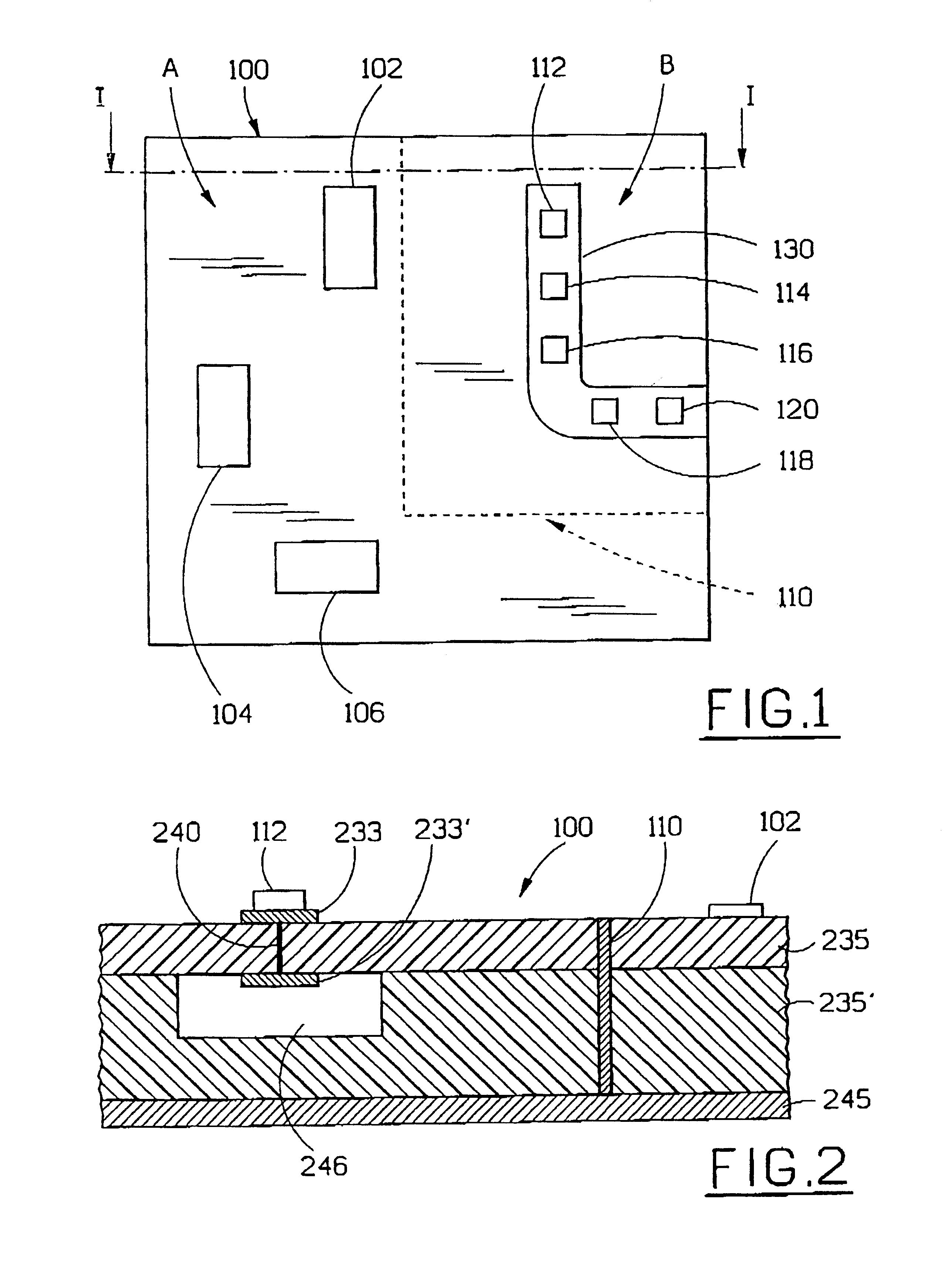
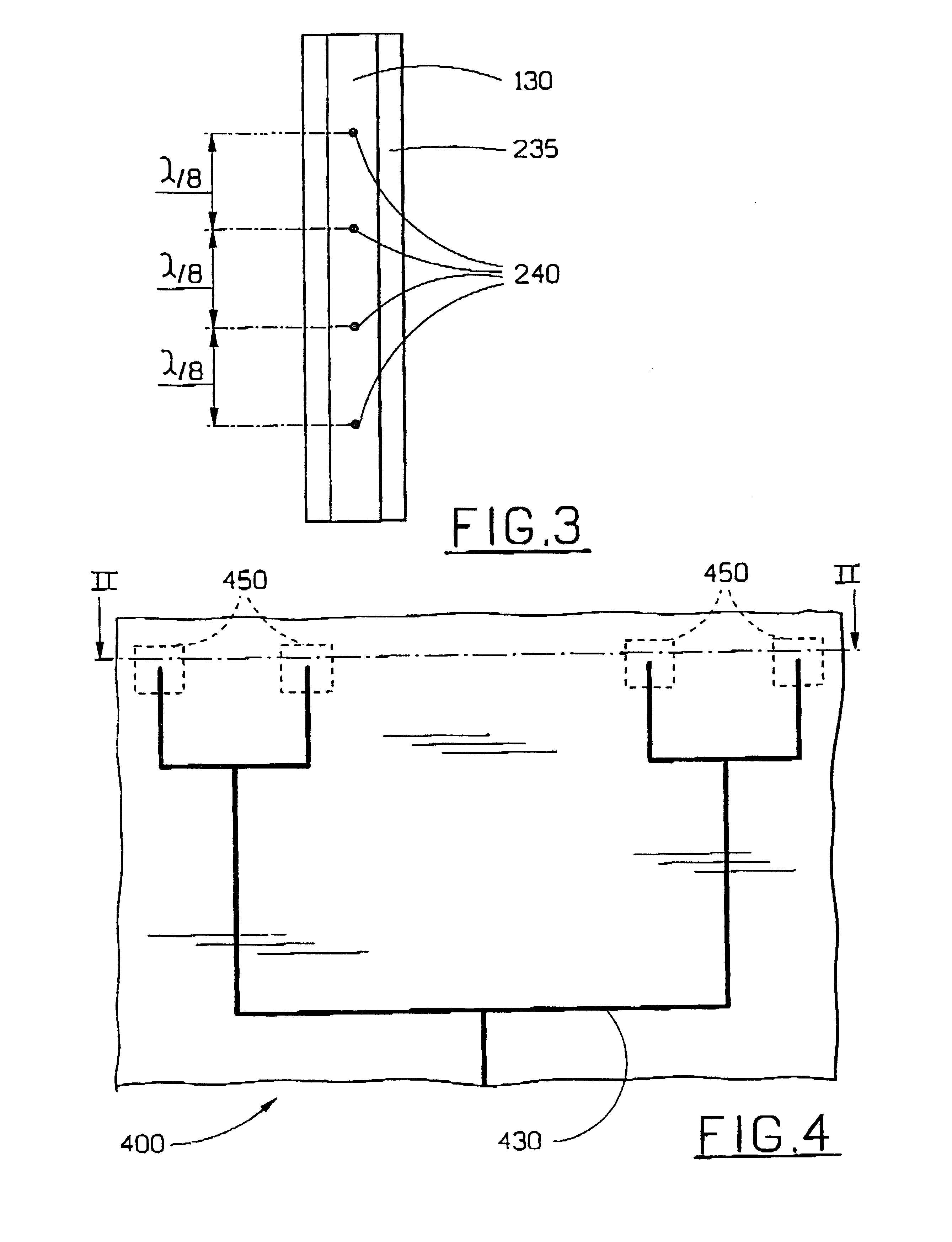
A problem that is solved by means of the present invention is therefore that of minimizing, in an arrangement made using microstrip technology, the field losses that are caused by the dielectric material on which the conductive material is arranged.

Another problem that is solved by means of the present invention is that of minimizing the influence of material variations in the dielectric material in a microstrip arrangement.

A further problem that is solved by means of the present invention is that of reducing the reflection losses that arise in a microstrip arrangement.

By solving the abovementioned problems, it is possible to make use, in microstrip arrangements, of the type of dielectric that is used in conventional circuit board technology. As a result of this, microwave circuits can be connected to microstrip arrangements arranged on circuit boards that are manufactured using conventional circuit board technology. Furthermore, microstrip antennas can be manufactured using convent...


PUM


Abstract

The invention relates to a microstrip arrangement comprising a first and a second microstrip conductor. The two microstrip conductors have essentially the same dimensions in their longitudinal direction and transverse direction, and are galvanically interconnected by means of at least one connection. The two microstrip conductors also extend essentially parallel to one another on either side of a dielectric material. As a result of this design of the microstrip arrangement, the field losses and also other influences caused by the dielectric material will be very considerably reduced, and in practice a resultant microstrip arrangement is obtained, which, with regard to its electrical performance, appears to be suspended in the air. Preferred embodiments comprise a microstrip antenna, a circuit board and a conductor application.

Description

The present invention relates to a microstrip arrangement, preferably for use in a circuit board or in an antenna arrangement.STATE OF THE ARTMicrostrip technology is commonly used in arrangements within higher frequency ranges, for example the microwave range. Microstrip arrangements usually comprise a plane layer of an electrically conductive material arranged on a substrate of dielectric material. Common areas of application for microstrip arrangements are antennas and also circuit technology within the microwave range.An extremely important and cost-influencing parameter in previously known microstrip arrangements is the material that is used as dielectric substrate. The material for the dielectric substrate is extremely important in known microstrip arrangements on account of inter alia the field losses that occur in the dielectric. In order to minimize these field losses, it has been necessary to use relatively expensive dielectric materials in previously known microstrip arra...

Claims


Application Information

Patent Timeline
Patent Type & Authority Patents(United States)
IPC IPC(8): H01P3/08H01Q13/20H01Q21/00H01Q9/04H05K1/02
CPCH01P3/084H01Q9/0407H01Q9/045H01Q13/206H01Q21/0081H05K1/0245H05K1/024H05K2201/09972H05K2201/09618H05K2201/09672H05K2201/0979H05K2201/098
Inventor BERGSTEDT, LEIFGEORGIAN, SPARTAK
Owner HIGHBRIDGE PRINCIPAL STRATEGIES LLC AS COLLATERAL AGENT
Why Eureka
Try Eureka