Air conditioner

a technology for air conditioners and air conditioners, applied in the field of air conditioners, can solve the problems of deteriorating comfort, difficult individual temperature control of each air conditioning zone, and inability to supply individual air streams to the air conditioning zone,

Inactive Publication Date: 2001-08-14
DAIKIN IND LTD
View PDF10 Cites 16 Cited by
  • Summary
  • Abstract
  • Description
  • Claims
  • Application Information

AI Technical Summary

Benefits of technology

Specifically, conditioned air streams having different temperatures in response to different heat loads in the respective rooms can be produced. And, many kinds of temperature-adjusted conditioned air streams can be delivered to the rooms, respectively. This achieves improved comfortableness in the respective rooms.
If the heat-recycling heat exchanger is provided, air dehumidified in the heat-use-side heat exchanger can be heated again in the heat-recycling heat exchanger. Accordingly, humidity-adjusted conditioned air can be delivered to the room. This enables control of not only the room temperature but also the room humidity, thereby achieving further improved comfortableness.
If the refrigerant circuitry is provided with the connection ports, various kinds of additional heat exchangers can be connected to the refrigerant circuitry. This achieves fostered versatility and increased installation flexibility.
This facilitates manufacturing process, increases product accuracy and reduces manufacturing costs.
If the suction ports and the like for the plurality of heat-use-side spaces are formed in symmetric positions, the port type such as a suction port can be readily discriminated from the other port type. This prevents misconnection of a suction duct or the like. Further, in this case, the weight can be evenly distributed. This weight distribution can stabilize the position of the air conditioner after installed.

Problems solved by technology

This arises a problem that individual temperature control on each of the air conditioning zones is very much difficult.
In this case, the air conditioning zones cannot be supplied individually with conditioned air streams at temperatures in response to the heat loads thereof.
This arises a problem of deteriorating comfortableness.

Method used


Image

  • Air conditioner
  • Air conditioner
  • Air conditioner

Examples


embodiment 1

Modification of Embodiment 1

The above-mentioned space-heating heat exchanger (11) is a heat exchanger for a space-heating operation only. However, the space-heating heat exchanger (11) may be used as a heat exchanger for a dehumidifying operation, or may be used as a heat exchanger for both space-heating and dehumidifying operations.

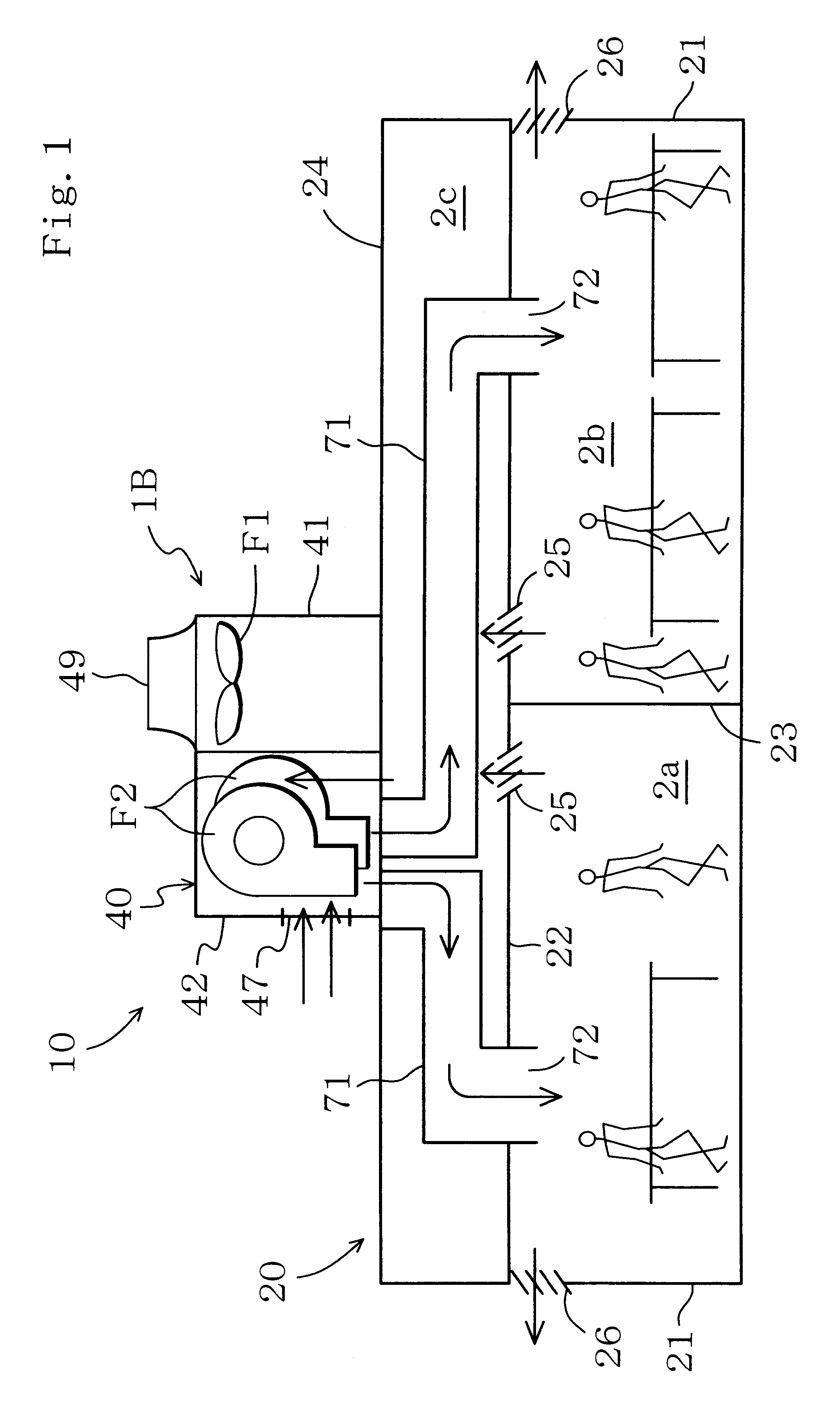
Specifically, in a dehumidifying operation, when the refrigerant circuitry (60) is driven, refrigerant is cooled in the heat-use-side heat exchanger (65) to dehumidify room air and outdoor air. Thereafter, the cooled air is heated again in the space-heating heat exchanger (11). This heating of air enables conditioned air having substantially the same temperature as room temperature to be delivered to the respective air conditioning zones (2a, 2b).

As a result, not only room temperature but also room humidity can be controlled. Accordingly, further improved comfortableness can be achieved.

embodiment 2

Next, a detailed description will be given to Embodiment 2 of the present invention with reference to the drawing.

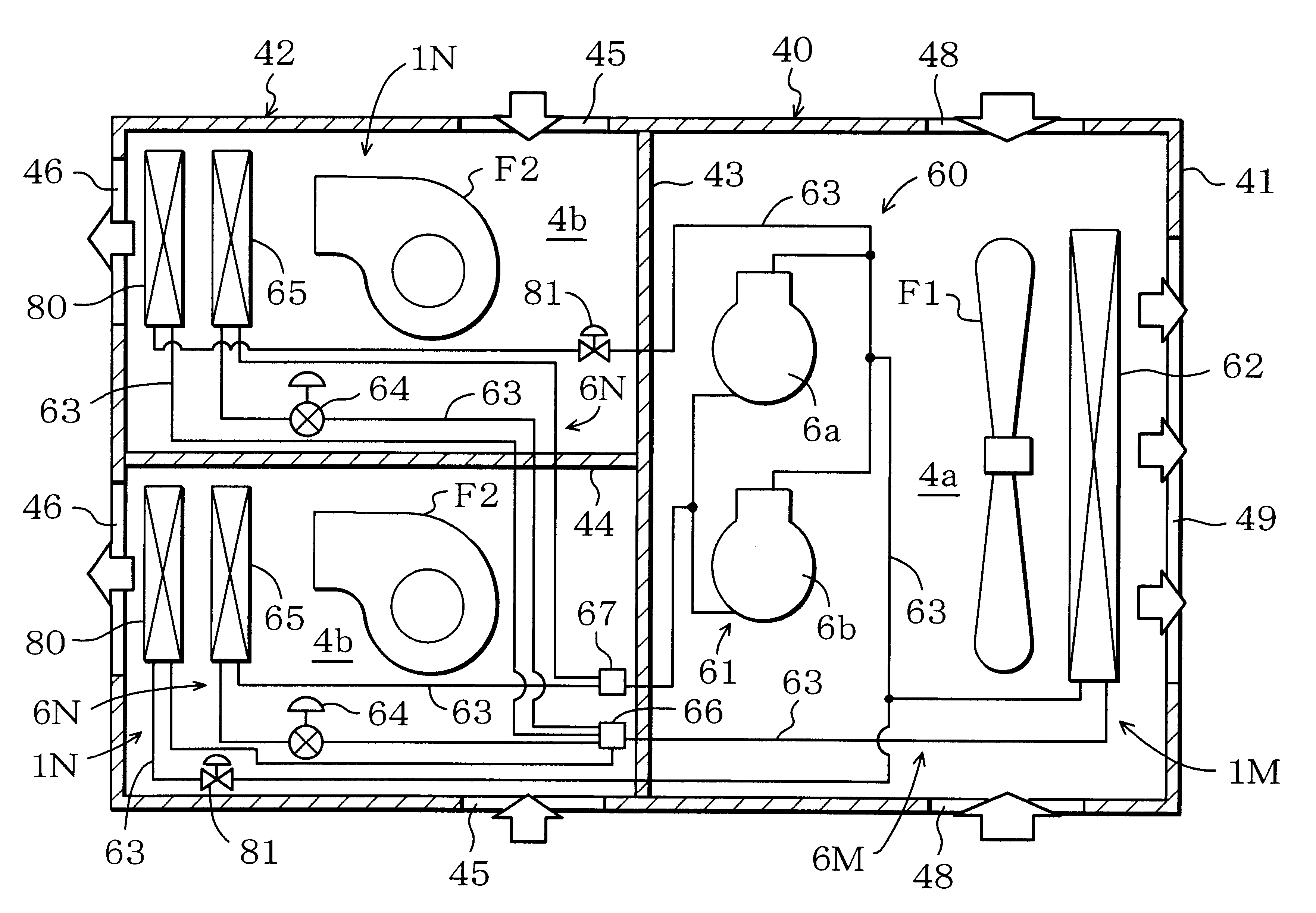
As shown in FIG. 4, in the present embodiment, heat-recycling heat exchangers (80, 80) are provided instead of the space-heating heat exchangers (11, 11) of Embodiment 1.

The heat-recycling heat exchangers (80, 80) are individually provided in the heat-use-side units (1N, 1N) and are individually disposed in the heat-use-side spaces (4b, 4b). One end of the heat-recycling heat exchanger (80) is connected to the discharge side of the compression mechanism (61), with a shut-off valve (81) interposed therebetween, through a piece of the refrigerant piping (63). The other end of the heat-recycling heat exchanger (80) is connected to the branch part (66) through another piece of the refrigerant piping (63).

With this arrangement, in carrying out a dehumidifying operation, the shut-off valves (81, 81) are opened and the compression mechanism (61) is driven. Refrigerant discharge...

embodiment 3

Next, a detailed description will be given to Embodiment 3 of the present invention with reference to the drawing.

As shown in FIG. 5, in the present embodiment, an additional heat exchanger (83) is provided in the refrigerant circuitry (60) of Embodiment 1.

The additional heat exchanger (83) is formed by, for example, a heat exchanger for a kitchen or a heat exchanger in an open-air treatment unit. The refrigerant circuitry (60) is provided with two connection ports (84, 84). The additional heat exchanger (83) is connected to the connection ports (83, 83) through pieces of the refrigerant piping (63, 63).

In the case where the additional heat exchanger (83) is a heat exchanger for a kitchen, refrigerant is heat-exchanged with room air in the kitchen to cool the kitchen. On the other hand, in the case where the additional heat exchanger (83) is a heat exchanger in an open-air treatment unit, the open-air treatment unit is installed in a ventilating opening. The open-air treatment unit ...


PUM


Abstract

A heat-source-side space and two heat-use-side spaces are formed in a casing. A heat-source-side heat exchanger is contained in the heat-source-side space, and heat-use-side heat exchangers are individually contained in the heat-use-side spaces. The casing is formed with a plurality of suction ports for room air and a plurality of delivery ports for conditioned air. The suction ports and the delivery ports are individually connected to ducts communicating with rooms. The heat-source-side heat exchanger and the plurality of heat-use-side heat exchangers constitute refrigerant circuitry.

Description

This invention relates to an air conditioner and particularly relates to an air conditioner including a plurality of heat-use-side heat exchangers.DESCRIPTION OF THE PRIOR ARTThere is a conventional type air conditioner having an heat-use-side unit as an indoor unit and a duct connected to the heat-use-side unit and communicated with rooms (See, for example, Japanese Patent Application Laid-Open Gazette No.4-270851).Conditioned air produced in the heat-use-side unit is delivered from the heat-use-side unit to the rooms through the duct. The rooms are air-conditioned by the conditioned air.Another example of conventional air conditioners is of a rooftop type. In the rooftop type air conditioner, a heat-source-side unit and a heat-use-side unit are contained in a single casing thereby forming a main body of the air conditioner. The main body is installed on a rooftop of a building. A duct is extended from the main body to the rooms in the building. Conditioned air produced in the main...

Claims


Application Information

Patent Timeline
Patent Type & Authority Patents(United States)
IPC IPC(8): F25B6/00F24F3/044F24F3/052F25B5/02F25B5/00F25B41/04
CPCF24F3/044F24F3/0527F25B6/00F25B5/02F25B41/04F25B41/24
Inventor MIKI, HIROSHIFUJIWARA, YASUSHIYOSHIMITSU, SATORUMATSUMOTO, AKIHITO
Owner DAIKIN IND LTD
Why Eureka
Try Eureka