Supercharge Your Innovation With Domain-Expert AI Agents!

Shift control apparatus for transmission

Inactive Publication Date: 2001-08-21
AISIN AI CO LTD
View PDF10 Cites 53 Cited by
  • Summary
  • Abstract
  • Description
  • Claims
  • Application Information

AI Technical Summary

Problems solved by technology

If the operate pressure of the actuator upon the shifting push-in of the sleeve 18 is decreased, there is fear that the shift push-in of the sleeve 18 may become inaccurate or longer time is required for the shift push-in of the sleeve 18.
However, the speed-change shock or noise may be generated even in this adjusted value P.sub.1 depending on the rotate speed of the gear piece 24 and the like.
Same problem may occur in a speed change (shift-up and shift-down) without the select operation.
That is, the shock / noise may occur in all kinds of the shift operation.

Method used


Image

  • Shift control apparatus for transmission
  • Shift control apparatus for transmission
  • Shift control apparatus for transmission

Examples


Embodiment Construction

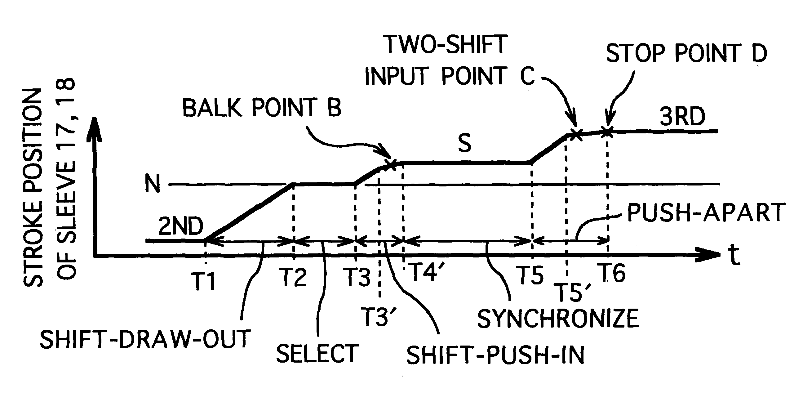
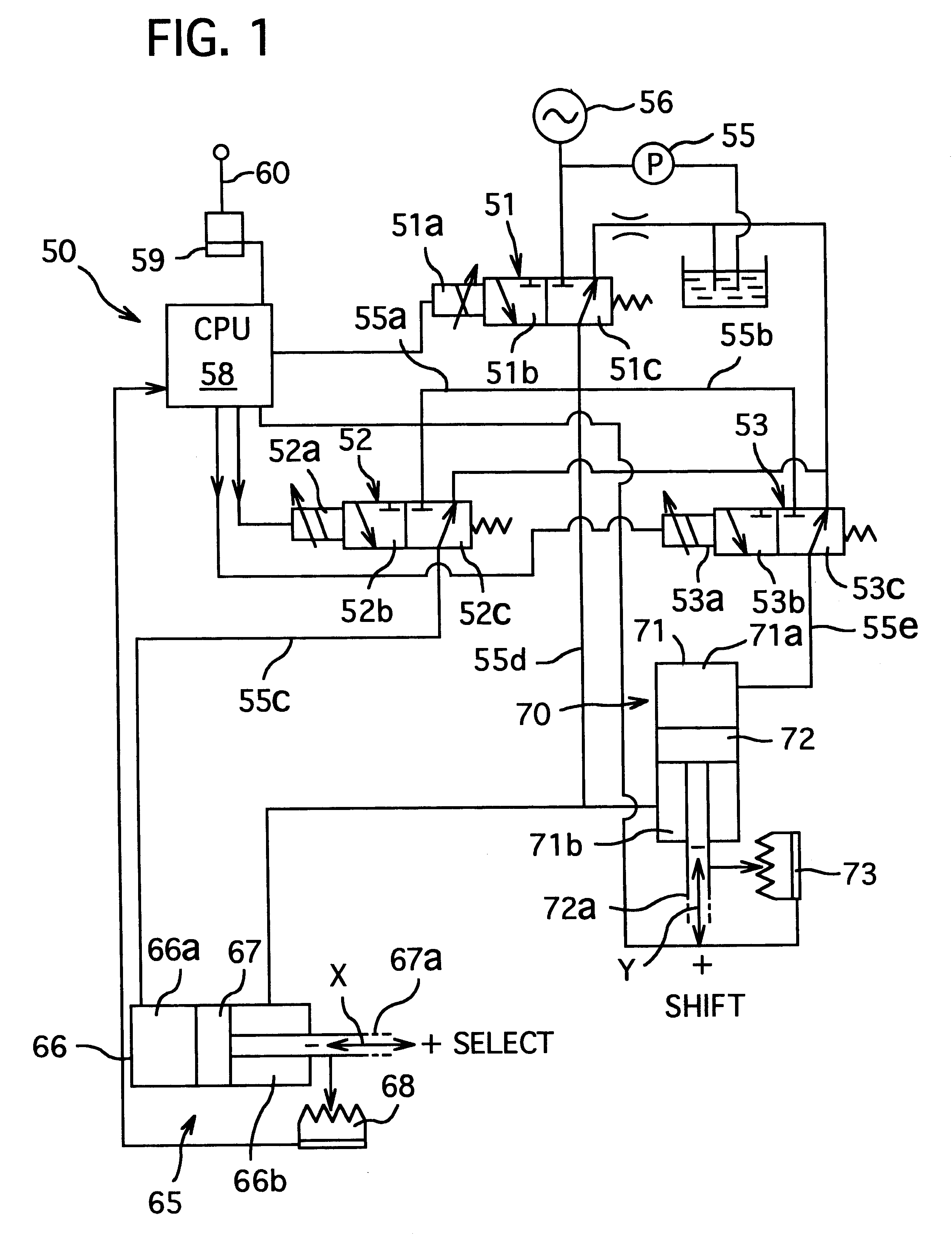
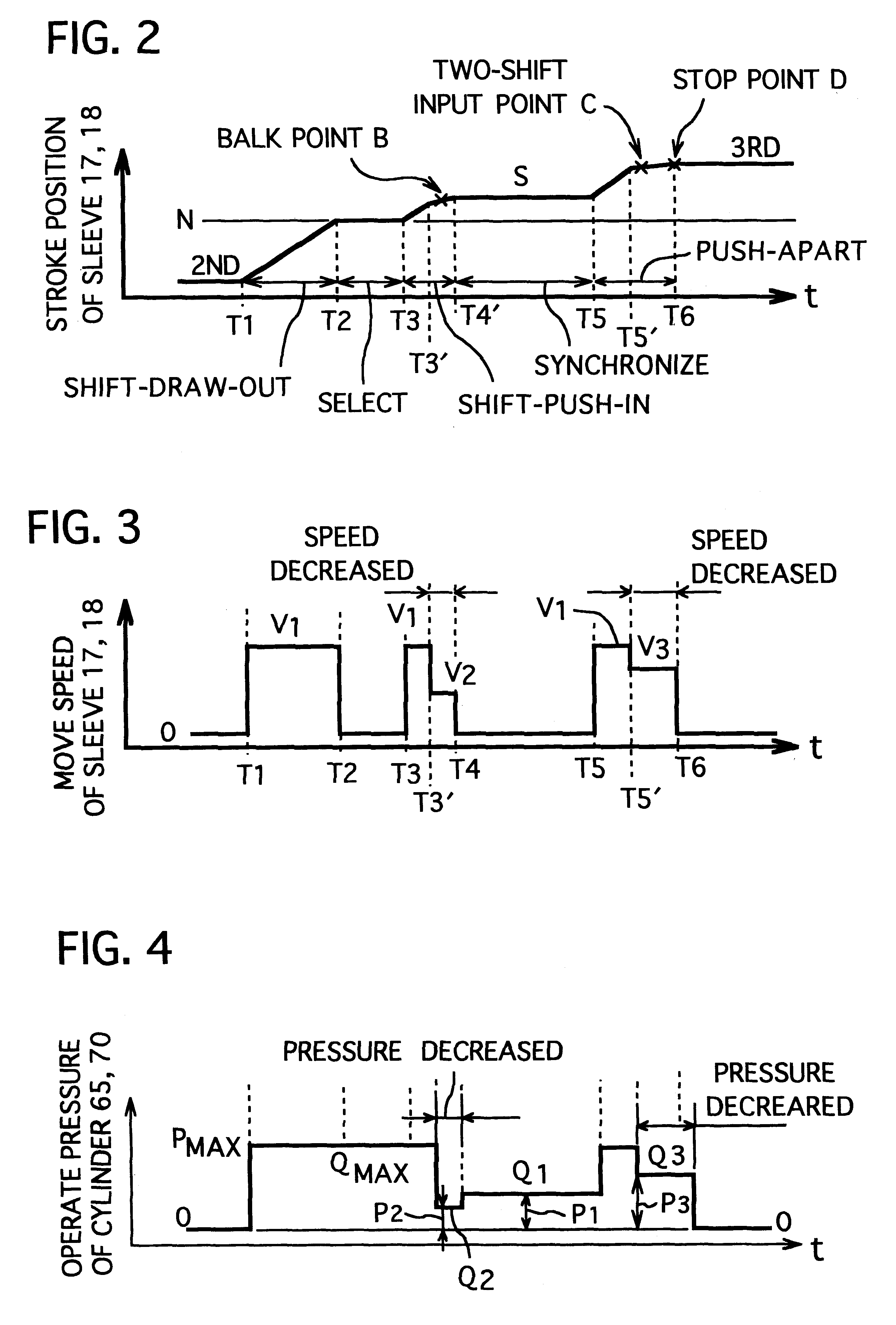
Hereinafter, a preferred embodiment of the present invention will be explained with reference to attached FIGS. 1 to 4. However, it is noted that this embodiment should not be interpreted to limit the present invention.

A shift control apparatus of this embodiment is comprised of an operate lever 60 and a switch 59; a control means 50 including a master valve 51, a pair of proportional flow-amount valves 52 and 53 and a controller 58; and an actuator including an oil pump 55 driven by an electric motor (not shown), an accumulator 56, a select cylinder 65 and a shift cylinder 70 etc., and drives the shifting of the sleeves 17 of the synchro mechanism 15 and the sleeves 18 of the synchro mechanism 16 shown in FIG. 5.

The master valve 51 is a solenoid-type pressure control valve which outputs a pressure proportional to a solenoid current applied, and having a solenoid 51a, a left position 51b, a right position 51c and a neutral position (not shown). The master valve 51 is switched to the...


PUM


Abstract

The present invention intends to provide a shift control apparatus for transmission which can reduce or prevent the speed-change shock and / or noise at the balk point where the sleeve engages with the ring in the shift push-in process.In order to achieve the above object, a shift control apparatus for a transmission comprises a plural sets of paired free-rotate gears, a plural sleeves 17, 18, a plural sets of paired synchronize rings 27 to 29, an actuator 65, 70 for actuating the sleeve, a control means 50 for controlling the actuator based on a speed-change command. The control means 50 controls the actuator 70 so that the sleeve 18 is driven by a first drive force Qmax upon starting of a speed-change operation, and is driven by a second drive force Q2 smaller than the first drive force at least during a first time period T3' to T4' from a time before a balk point B of the sleeve where the sleeve engages with the synchronize ring in a shift push-in operation.

Description

1. Field of the InventionThe present invention relates to a shift Control Apparatus for a speed change apparatus (transmission), especially for a synchromesh type transmission.2. Related ArtIn a synchromesh-type transmission, as shown in FIG. 5, sleeves 17 and 18 which constitute a part of a cynchro mechanisms 15 and 16 are pressed to one of free-rotate gear groups of a 2nd-shift gear 11, a 3rd-shift gear 12 and a 4th-shift gear 13 (a 1st-shift gear and the like are not shown) mounted onto an output shaft 30 disposed coaxial with an input shaft 10, thereby rotating the free-rotate gear together with the output shaft 30. On a counter shaft 40 disposed parallel to the output shaft 30, gears 41, 42 and 43 are mounted to mesh with the above gears 11, 12 and 13 respectively.The above synchromesh transmission is mainly comprised of clutch hubs 21 and 22, sleeves 17 and 18, second speed to fourth speed gear pieces 23 to 25, three synchronize rings 27 to 29. In detail, the clutch hubs 21 an...

Claims


Application Information

Patent Timeline
IPC IPC(8): F16H61/28F16H59/68F16H61/30F16D23/06F16H3/12F16H61/00F16H61/08
CPCF16H61/2807F16H61/30Y10T74/19251F16H2061/2823F16H2059/6807
Inventor UEDA, YUKIOITO, YOSHIKI
Owner AISIN AI CO LTD
Features
  • R&D
  • Intellectual Property
  • Life Sciences
  • Materials
  • Tech Scout
  • Unparalleled Data Quality
  • Higher Quality Content
  • 60% Fewer Hallucinations
Learn More