Coordinate input device and method having first and second sampling devices which sample input data at staggered intervals

a technology of input data and sampling device, which is applied in the direction of instruments, computing, electric digital data processing, etc., can solve the problems of increasing storage capacity, inefficient operation, and processing taking a very long tim

Inactive Publication Date: 2001-08-21
CANON KK
View PDF10 Cites 87 Cited by
  • Summary
  • Abstract
  • Description
  • Claims
  • Application Information

AI Technical Summary

Problems solved by technology

Increase of the sampling points causes an increased work load on the host apparatus as well as an increase in storage capacity of a memory, resulting in inefficient operation.
Since the calculation of the vector involves matrix calculation, the processing will take a very long time.
This also causes an increased work load on the host apparatus, resulting in inefficient operation as well as reduction in real-time operativity.
In such an exchange configuration, however, since the coordinate information transmitted from the coordinate input device to the host apparatus is specified on an input surface of the coordinate input device and continuously sent at each predetermined, constant rate, e.g., at a rate of 100 points / sec., its quantity or quality may be unsuitable for some information processing.
In this case, apparently displayed characters can be reproduced on the display screen, but other problems arise that processing time for the curve interpolation takes much longer and real-time operativity until displayed after input is impaired.
In this case, the host apparatus is required to temporarily store all the coordinate information from the coordinate input device without fail, therefore, still another problem arises that a trace required for a long input time involves an increasing quantity of information.
Likewise, this problem occurs when the host apparatus transfers information to an external device.
Furthermore, the use of all the coordinate information to execute character or graph recognition in the same manner as aforementioned may be extremely wasteful in a case requiring high-speed operation at the beginning of the recognition processing step such as stroke matching or matching between initial and terminal points.
Thus, yet another problem arises that the coordinate information is either insufficient or wasteful for each individual step in one processing.
In such a case, since the coordinate data is transmitted from the coordinate input device to the host apparatus at a fixed time interval, a delay is produced in the coordinate data read-in process when the processing steps at the host apparatus are complicated.
Such a double display configuration, however, may provide a sense of incongruity to the operator due to a difference between two displayed traces.
Further, the host apparatus can not read all the coordinate data input at a short time interval while displaying the curve unless the processing speed of the CPU in the host apparatus is extremely high.
In this case, although the time interval at which the coordinate data are sequentially input may be extended to avoid the missing coordinate data, this causes a failure in tracing a curve faithful to the graph or character originally drawn or written by the operator.

Method used


Image

  • Coordinate input device and method having first and second sampling devices which sample input data at staggered intervals
  • Coordinate input device and method having first and second sampling devices which sample input data at staggered intervals
  • Coordinate input device and method having first and second sampling devices which sample input data at staggered intervals

Examples


first embodiment

(First Embodiment)

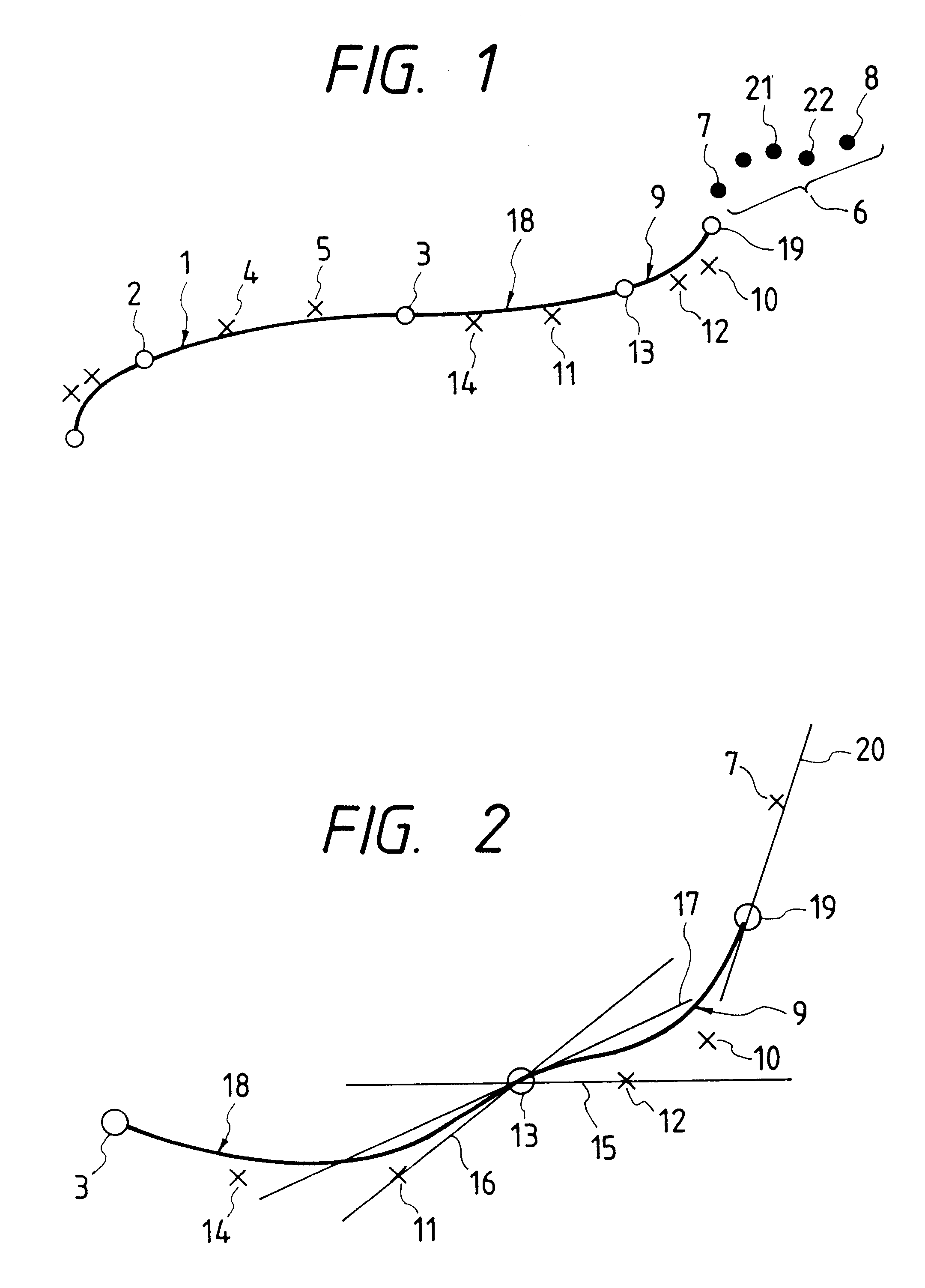
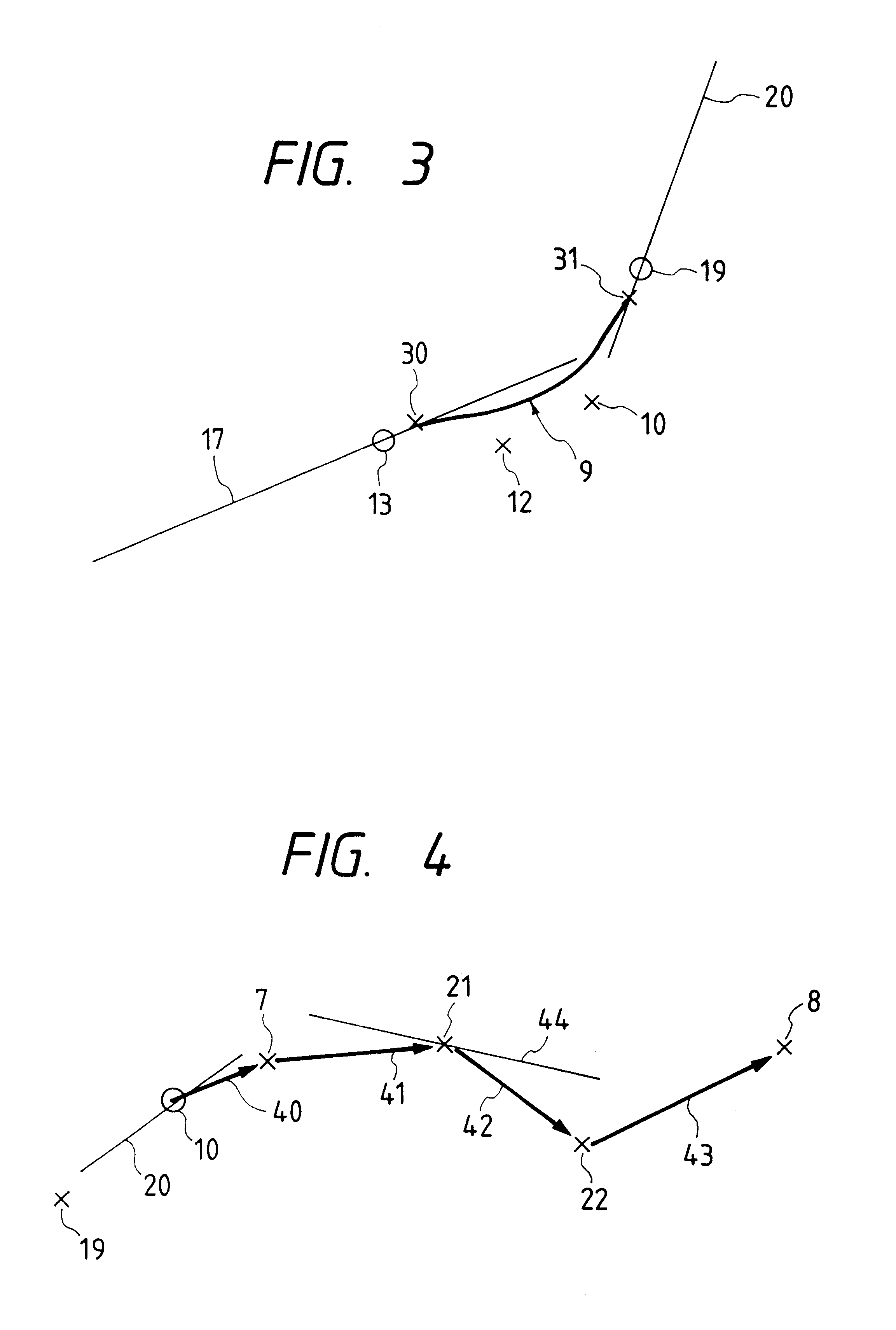
According to a first preferred embodiment of the present invention, a coordinate input device includes curve calculation means which starts calculating an approximate curve based on at least four points of coordinate data at the time when the four points of coordinate data have been generated.

The coordinate input device according to the embodiment also includes determination means for determining whether an angle difference between two straight lines is a predetermined value or more, in which one line is formed by a terminal point of the approximate and the previous point and the other line is formed by the terminal point and the subsequent point. If the angle difference is determined to be the predetermined value or more, the terminal point of the approximate curve will be changed to the previous one.

In the embodiment, the approximate curve may be selected among a Bezier curve, a three-dimensional spline curve and a B-spline curve.

Further, the coordinate input dev...

second embodiment

(Second Embodiment)

Next, a description will be made to a second embodiment in which coordinate output prior to execution of the curve processing are combined with continuous curve output in the first embodiment.

FIG. 8 is an illustration showing a relationship between a Bezier curve and points corresponding to respective coordinate data in the second embodiment of the present invention.

In FIG. 8, a Bezier curve 81 is formed by an initial point 82 and a terminal point 83, including apexes 84, 85. A point 86 is also displayed as coordinate data provisionally output.

In the case shown in FIG. 8, a certain amount of input coordinate data is converted into a Bezier curve in order of input as the coordinate data are output. As described above, the Bezier curve is determined by four points, namely, the initial point, terminal point and two apexes so that display points can be calculated therefrom. Time required for inputting the terminal point after the initial point was input is also output...

third embodiment

(Third Embodiment)

Referring to FIGS. 9 through 11, a third embodiment of the present invention will be described below.

FIG. 9 is a schematic block diagram showing a system structure including a host apparatus and a coordinate input device according to the third embodiment; FIGS. 10A and 10B are flowcharts showing operation in the embodiment; and FIG. 11 is an illustration of coordinate strings which represent output information from the coordinate input device according to the embodiment.

In FIG. 9, the coordinate input device 101 includes a coordinate detector 102 and a coordinate discriminator 103 for determining whether or not the coordinates detected by the coordinate detector 102 should be output. The coordinate detector 102, which may be constituted with one of well-known means, is connected to the input of the coordinate discriminator 103. An angle processor 104 and a counter 105 are also connected to the input of the coordinate discriminator 103. The angle processor 104 calcu...


PUM


Abstract

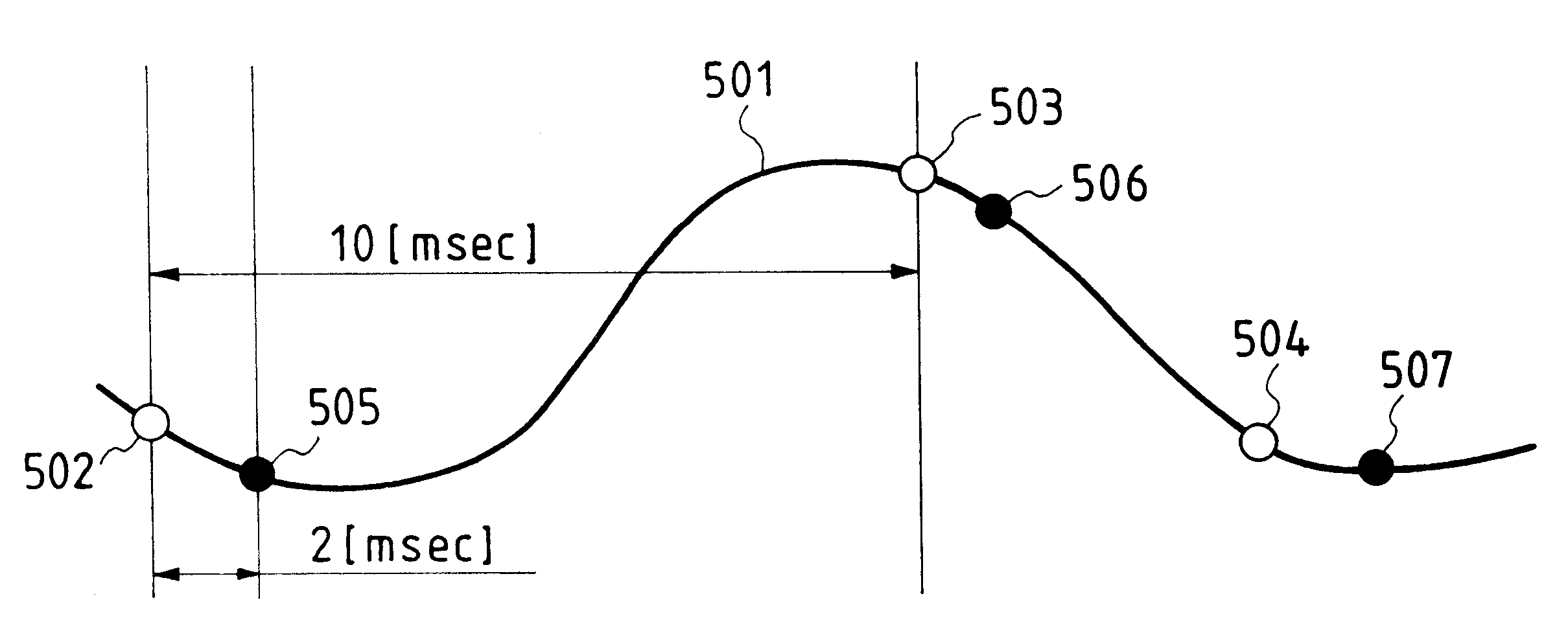
A coordinate input device interpolates sampling data, using less input data and simpler computing. The input data (coordinate information indicative of an input trace) are sampled both with a predetermined cycle (Tn), and at the end of a predetermined time interval after the sampling of the cycle Tn is complete. As a result of the two different samplings, not only the coordinate point determined by the sampling of cycle Tn, but also information indicative of a tangent vector at each coordinate point on the input trace are obtained. The coordinate point and the associated tangent vector information are thus output, so that a trace more faithful to the input trace is obtained using fewer coordinate points.

Description

BACKGROUND OF THE INVENTION1. Field of the InventionThis invention relates to coordinate input device and method for generating data based on coordinate positions specified by an operator.2. Related Background ArtThere are known in the art digitizers which are used as sampling devices. One such device permits handwriting input by the operator using an input appliance such as a stylus pen. The device of this type provides handwriting computing applications, differently from that using a keyboard, by displaying an input trace to a host computer based on coordinate data from the coordinate input device, or by recognizing strings of input coordinate points as a character.The coordinate input device referred to herein is configured to transmit, to the host computer, an X-Y coordinate pair indicative of a position of the stylus pen, the X-Y coordinate system using a certain point in the input area of the device as the origin, every predetermined time or when a change in the input point be...

Claims


Application Information

Patent Timeline
Patent Type & Authority Patents(United States)
IPC IPC(8): G06F3/033G06F3/0488
CPCG06F3/04883G06F3/0488G06F3/041
Inventor TANAKA, ATSUSHITATSUMI, EISAKUMORI, SHIGEKINAGASAKI, KATSUHIKO
Owner CANON KK
Why Eureka
Try Eureka