
Locking pliers with extended grip

a technology of extended grip and pliers, which is applied in the direction of pliers, screwdrivers, wrenches, etc., can solve the problems of separate pieces, excessive weight of enlarged pliers, and awkward use of many applications, so as to improve the ergonomics of the grip

Inactive Publication Date: 2001-08-28
BLACK & DECKER INC
View PDF11 Cites 30 Cited by
  • Summary
  • Abstract
  • Description
  • Claims
  • Application Information

AI Technical Summary

Benefits of technology

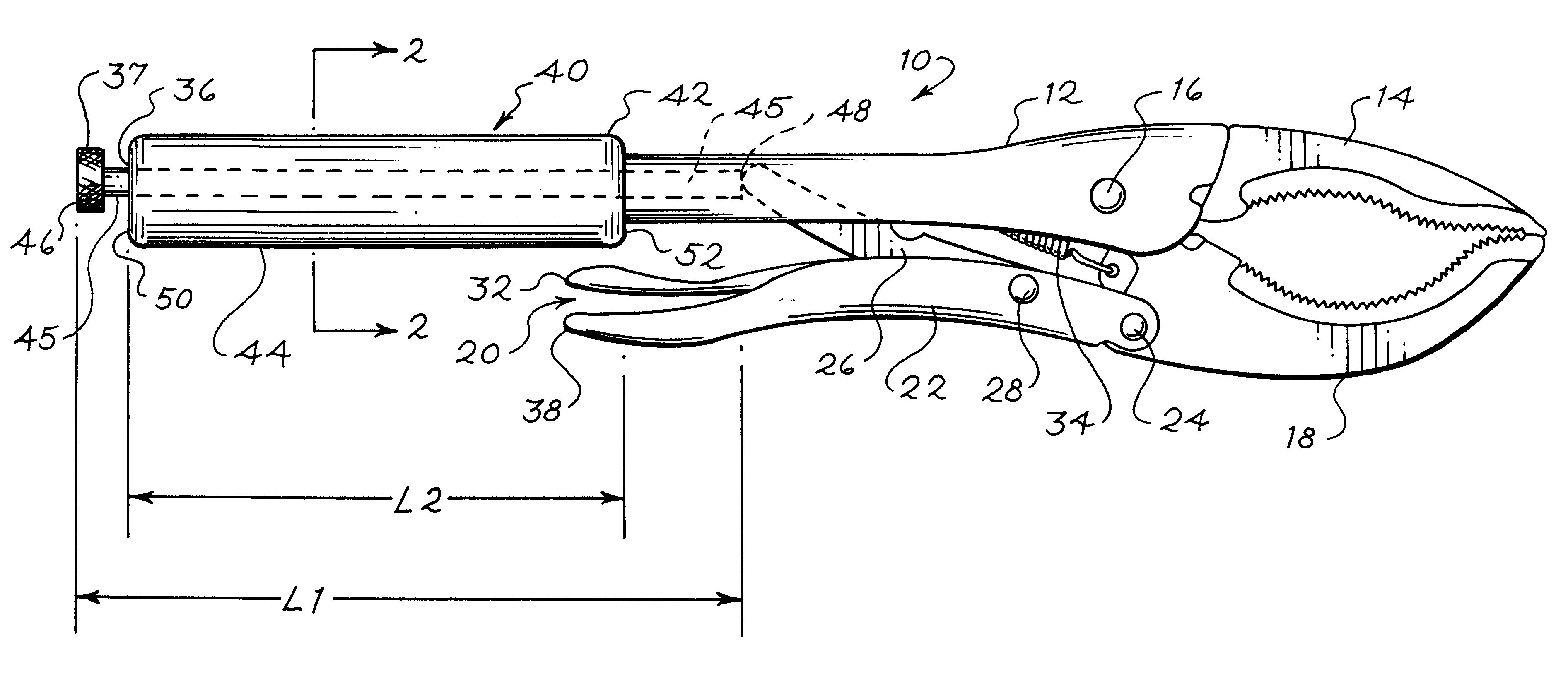
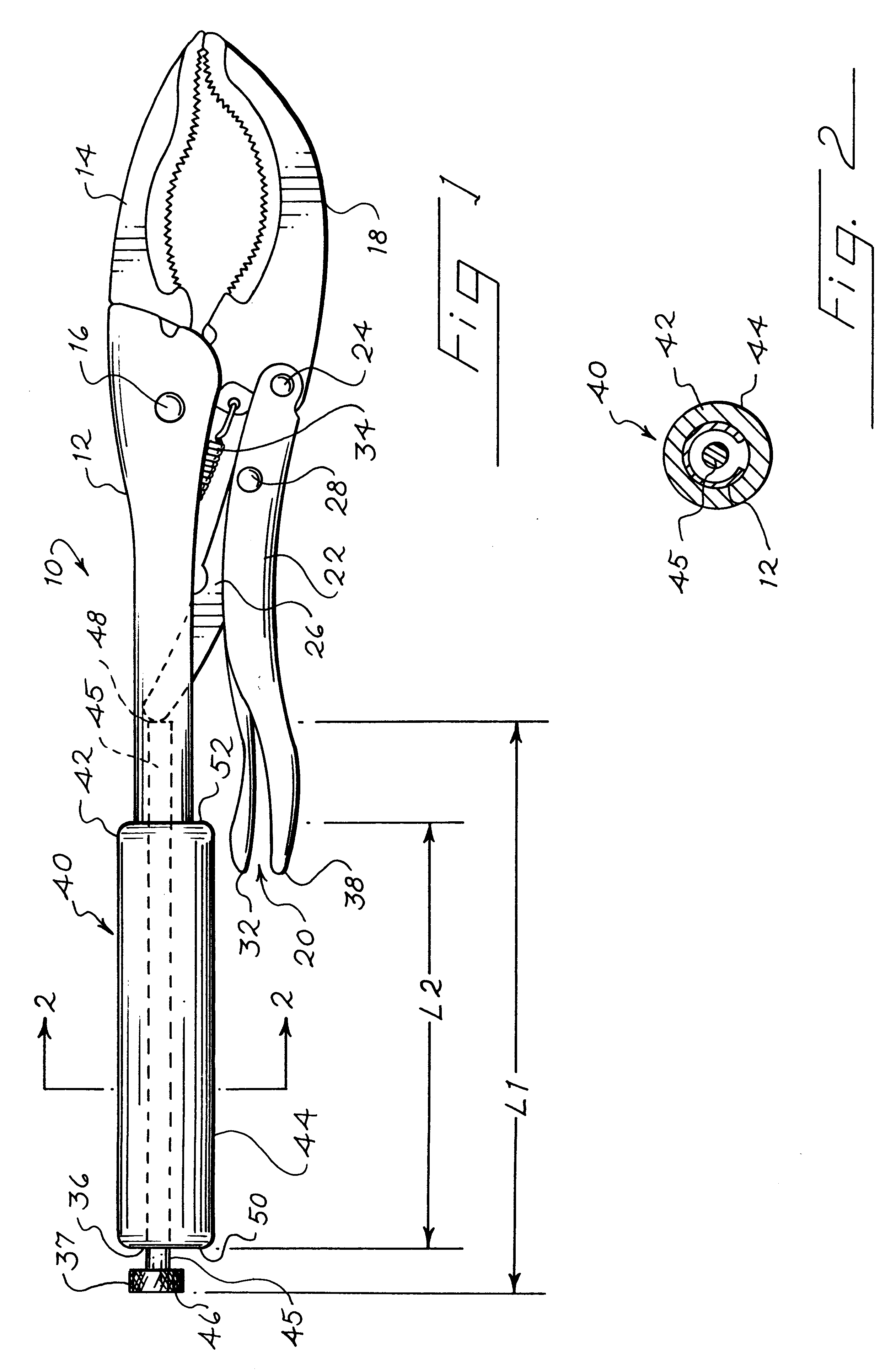
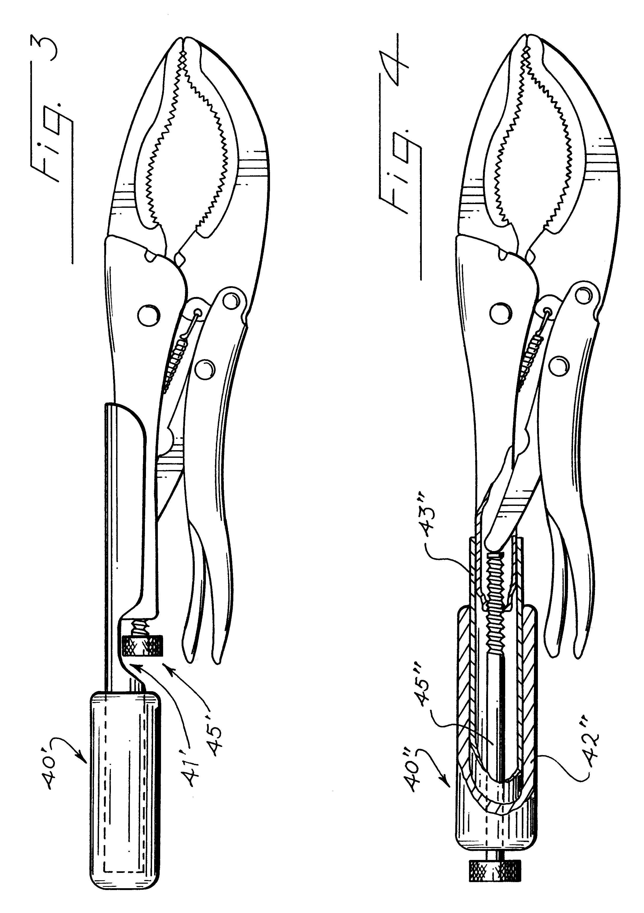
By way of introduction, the preferred embodiments described below are locking pliers having an over-center locking mechanism, a lever, and a body that forms an extended grip. This grip extends substantially beyond the outermost end of the lever, and the grip is configured such that the adjustment screw of the over-center locking mechanism is readily accessible. Preferably, the grip is covered with a resilient cushioning element to improve the ergonomics of the grip.

Problems solved by technology

However, if the locking pliers shown in U.S. Pat. No. 5,351,585 were simply enlarged in scale, the enlarged pliers would be excessively heavy and awkward to use for many applications.
Pipes of this type provide the disadvantage that they fit around the adjustment screw and that they are separate pieces.
It is therefore not possible to adjust the closed position of the movable jaw with the adjustment screw when a pipe of the type described above is positioned on the body of the locking pliers.

Method used


Image

  • Locking pliers with extended grip
  • Locking pliers with extended grip
  • Locking pliers with extended grip

Examples


Embodiment Construction

As shown in FIG. 1, a locking pliers 10 includes a body 12 that rigidly supports a fixed jaw 14 and defines a pivot axis 16. A movable jaw 18 is pivotably mounted to the body 12 to pivot about the pivot axis 16. The position of the movable jaw 18 with respect to the fixed jaw 14 is controlled by a lever 22 that is pivotably mounted to the movable jaw 18 at a pivot axis 24, and a locking mechanism such as an over-center toggle linkage 20. The linkage 20 includes a compression member such as a stub arm 26 that is pivotably mounted to the lever 22 at a pivot axis 28. A release lever 32 is pivotably mounted to the lever 22 to bear on the stub arm 26. A coil spring 34 operates as an extension spring to bias the movable jaw 18 to an open position.

The lever 22 and the stub shaft 26 operate to move the movable jaw 18 to a closed position when the lever 22 is moved generally parallel to the body 12. As used herein, the closed position of the jaw 18 is any position used to clamp a workpiece a...


PUM


Abstract

A locking pliers includes a body that supports a fixed jaw and a movable jaw. A lever is pivotably connected to the movable jaw, and a locking mechanism including a stub arm is coupled between the body and the lever to lock the jaws in a closed position. This locking mechanism includes an adjustment screw that is exposed at an end of the body remote from the fixed jaw. The body forms a resilient gripping surface that extends away from the exposed portion of the adjustment screw. This gripping surface extends beyond the end of the lever by at least about 4 inches such that the lever does not obstruct access to the grip. The user can place both hands on the grip to apply large torques to a clamped workpiece once the locking pliers has been locked in place on the workpiece.

Description

This invention relates to locking pliers, and in particular to an improved locking pliers that is well-suited to apply large torques to a workpiece locked in the pliers.Various types of locking pliers are well-known to those skilled in the art. See, for example, U.S. Pat. Nos. 5,351,585, 5,456,144 and 4,709,601, all assigned to the assignee of the present invention. Such locking pliers include an over-center toggle linkage that operates when closed to lock a movable jaw in an adjustable position with respect to a fixed jaw. Once the over-center toggle linkage has been closed, the locking pliers remains locked onto a workpiece, even if the user releases the pliers completely.The locking pliers shown in U.S. Pat. No. 5,351,585 includes large capacity jaws and is well-suited for use in plumbing and other applications where large torques are applied to the clamped workpiece. In such applications, it would on occasion be advantageous if the locking pliers provided a larger torque arm. Ho...

Claims


Application Information

Patent Timeline
Patent Type & Authority Patents(United States)
IPC IPC(8): B25B7/12B25B7/00B25G1/04B25G1/00
CPCB25B7/00B25G1/043B25B7/123B25B7/02
Inventor CHERVENAK, THOMAS M.
Owner BLACK & DECKER INC
Learn More