Thrust bearing to be used in a contaminated environment

a technology of contaminated environment and thrust bearing, which is applied in the direction of sliding contact bearings, dough extruders, mixing/kneading structural elements, etc., can solve the problems of limited capacity of existing pasta makers, messy and time-consuming use, and lack of versatility

Inactive Publication Date: 2001-08-28
LAURUS MASTER FUND
View PDF35 Cites 16 Cited by
  • Summary
  • Abstract
  • Description
  • Claims
  • Application Information

AI Technical Summary

Benefits of technology

The present inventions improve on prior devices in many areas.

Problems solved by technology

For the most part, existing pasta makers are limited in capacity, are messy and time consuming to use, and have little versatility.

Method used


Image

  • Thrust bearing to be used in a contaminated environment
  • Thrust bearing to be used in a contaminated environment
  • Thrust bearing to be used in a contaminated environment

Examples


Embodiment Construction

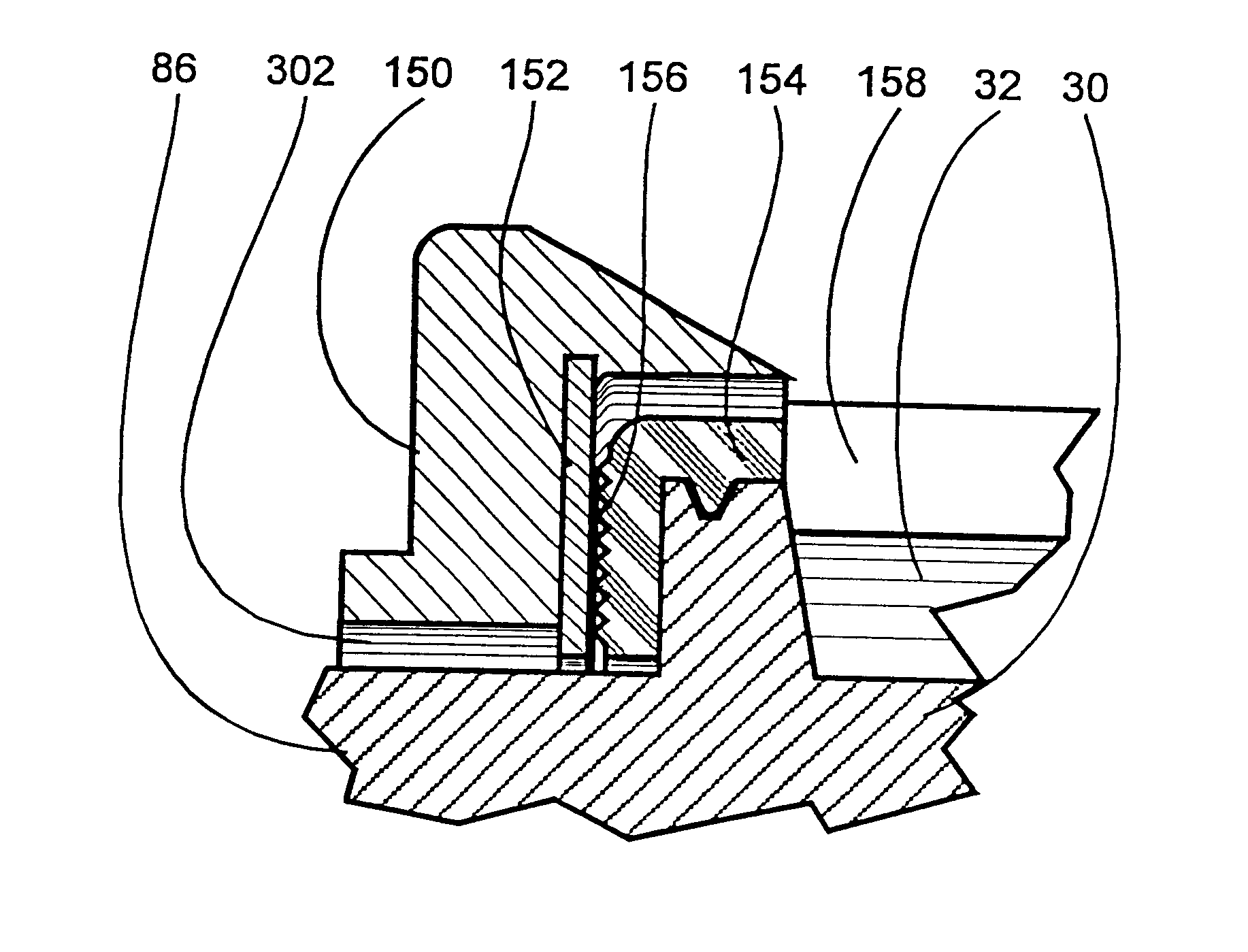
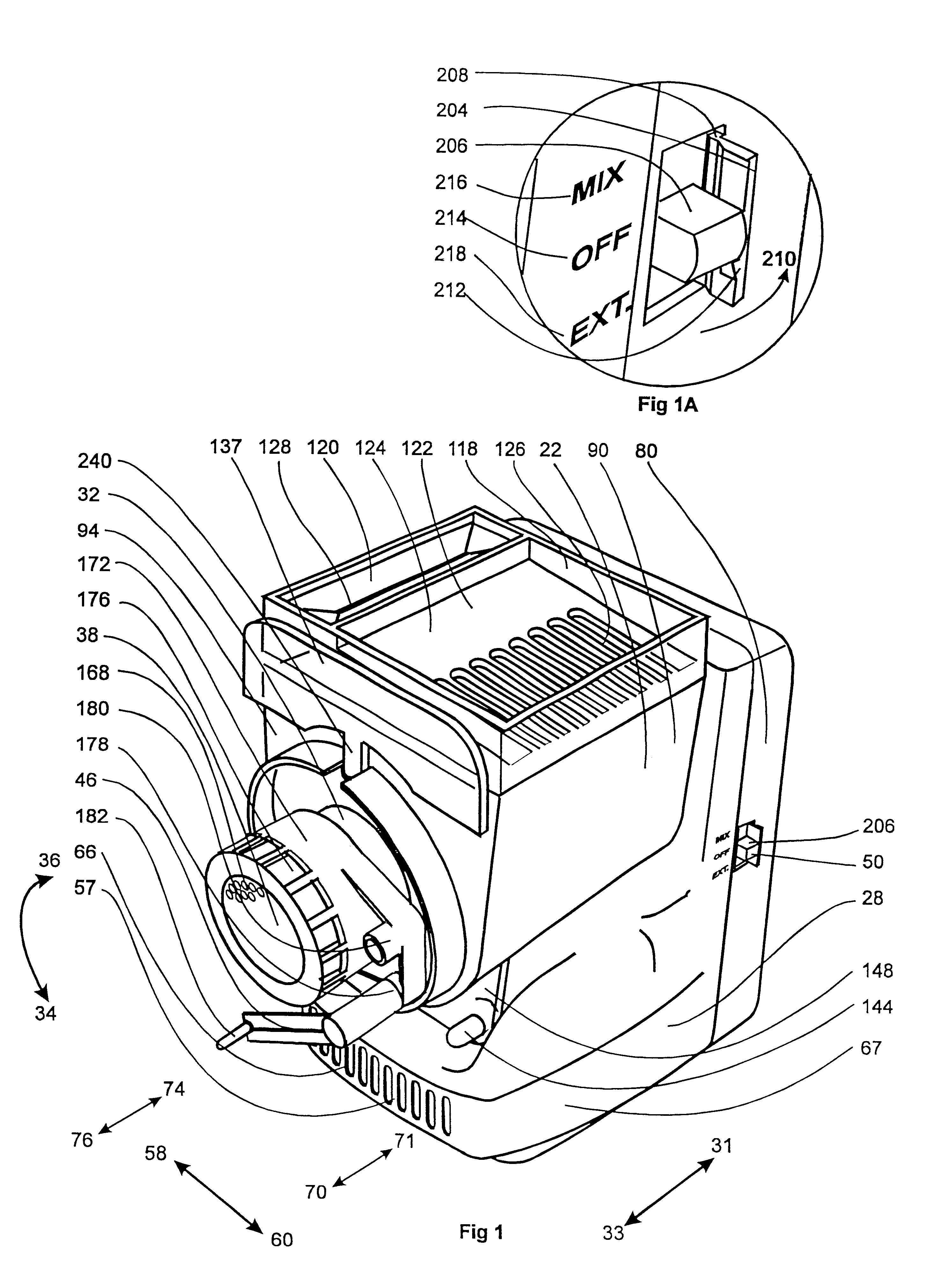
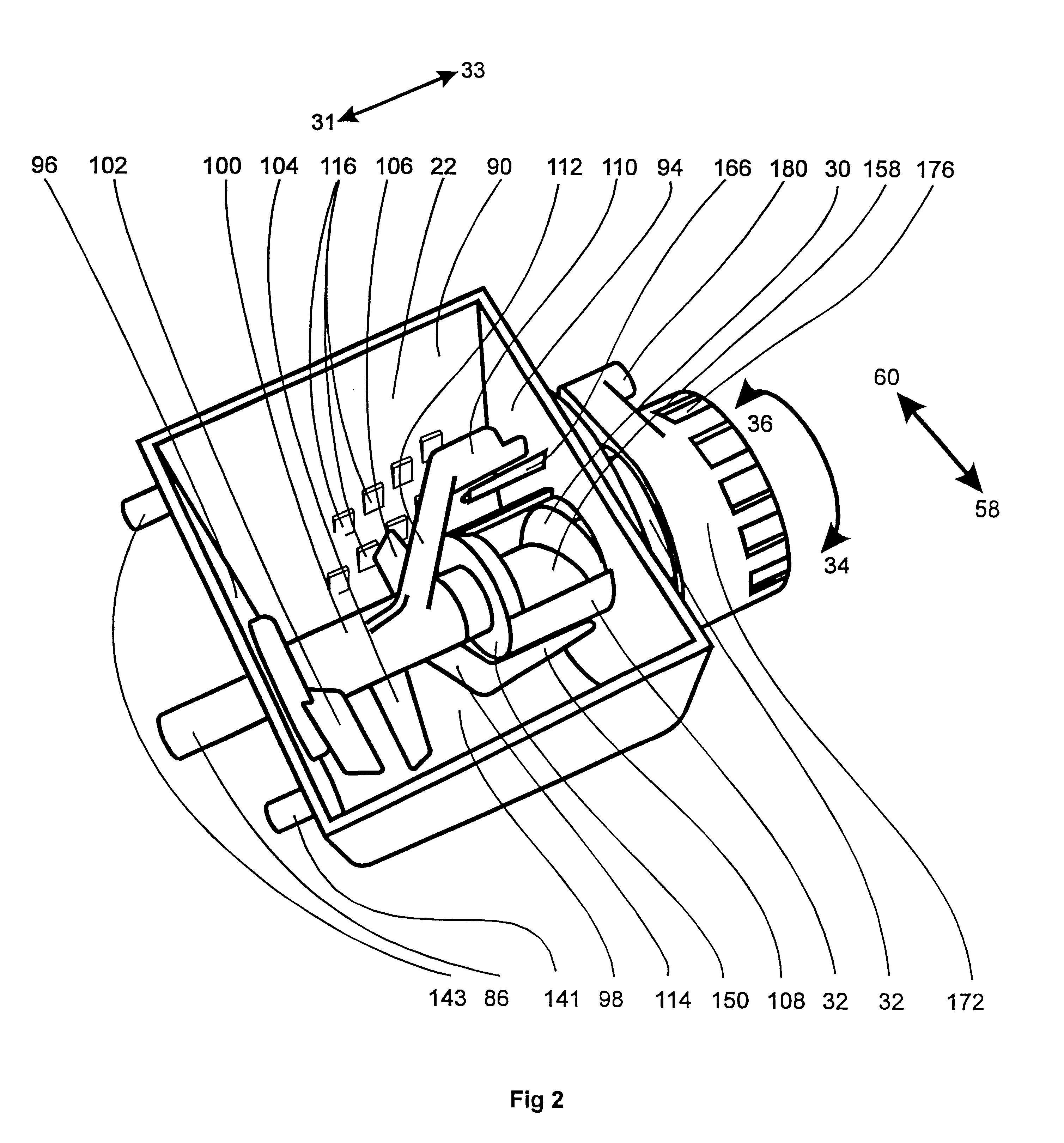
A preferred embodiment of the present inventions has a motor 24 rotated mixer and extruder 30 contained in clear polymeric enclosures 22, 32. The motor 24 and associated transmission 26 are contained in a stepped shaped enclosure 28 (see FIG. 10) which supports and cradles a clear plastic mixing bin 22 within its step. An auger extrusion screw 30 is contained in a cylindrical extruder housing 32 which protrudes into the front 33 of the bin 22 and continues out in front 33 of the flat front face 37 of the bin 22. Whether the embodiment mixes or extrudes is controlled by the direction of rotation 34, 36 of the motor 24 and consequent rotation of the mixing / feeding blades 102, 104, 106, 108, 110 and auger extrusion screw 30. Reverse rotation 34 of the blades 102, 104, 106, 108, 110 and screw 30 backs dough out of the extruder housing 32 and into the mixing bin 22; forward rotation 36 feeds the dough into the extruder screw 30 which in turn presses dough against and through the extrusio...


PUM

PropertyMeasurementUnit
input voltageaaaaaaaaaa
gate voltageaaaaaaaaaa

Abstract

A simplified trust bearing to be used in a dry powder contaminated environment such as a pasta maker, with the bearing comprising two plates contacting each other face-to-face and through such face-to-face contact transmitting an axial thrust load.

Description

BACKGROUND--FIELD OF THE INVENTIONThe present inventions are directed to home electric appliances to make pastas, pastries, cookies hors d'oeuvres and other extrudable food products.BACKGROUND--DESCRIPTION OF PRIOR ARTAutomatic home food mixing and extrusion appliances have been in common use for many years. Automatic pasta making appliances which both mix dough and automatically extrude dough through a die have been patented and in use in the U.S. at least since the late 1970s. In general such appliance have a configuration which includes a bin containing rotating blades, feeding an extrusion screw which forces the mixed materials through an extrusion die.For the most part, existing pasta makers are limited in capacity, are messy and time consuming to use, and have little versatility.SUMMARY OF INVENTIONThe present inventions improve on prior devices in many areas.Advantages of the present inventions will become apparent from the following description and illustrations of a preferr...

Claims


Application Information

Patent Timeline
Patent Type & Authority Patents(United States)
IPC IPC(8): F16C17/04A21C1/06A21C1/14A21C3/04A21C11/20B29C47/60
CPCA21C1/06A21C1/14A21C1/144A21C1/149A21C3/04A21C11/20B01F7/04B01F15/00844B01F15/027B01F15/0289F16C17/04F16C33/08A47J9/005F16C2314/00B01F27/70B01F35/512B01F35/752B01F35/754551
Inventor BACKUS, ALAN L.POPEIL, RONALD M.
Owner LAURUS MASTER FUND
Why Eureka
Try Eureka