Coil device and switching power supply apparatus using the same

a technology of switching power supply and coil, which is applied in the direction of electric variable regulation, process and machine control, instruments, etc., can solve the problems of difficult miniaturization of circuit board and switching power supply apparatus itself, large space requirements, and relatively high cost of transformers and choke coils

Inactive Publication Date: 2001-08-28
MURATA MFG CO LTD
View PDF10 Cites 57 Cited by
  • Summary
  • Abstract
  • Description
  • Claims
  • Application Information

AI Technical Summary

Benefits of technology

round one core, but similar to the effect of the invention already described, the interlinked magnetic fluxes cancel each other, or the voltages due to the induction cancel each other to form two independent transformers jointly using one core.
According to still another embodiment, a switching power supply apparatus includes a transformer for power transmission having a primary coil and a secondary coil, a main switch to control the current flowing from the input power supply into the primary coil, a rectifying and smoothing circuit which includes a choke coil and rectifies and smoothes the output of the secondary coil of the transformer for power transmission, and a control circuit to control the action of the main switch, the transformer for power transmission and the choke coil being formed of the coil device described above.
In this embodiment, the transformer for power transmission and the choke coil for rectifying and smoothing operation sharing the core comprise the coil device provided with the transformer which is formed on one core and equivalently generates no output voltage due to the induction. A core fitting space to a circuit substrate of the switching power supply apparatus is reduced thereby. Further, in the choke-input type rectifying and smoothing circuit, the secondary winding of the transformer for power transmission and the choke coil can be wired as one coil device in the manufacturing stage.
Alternatively, in the switching power supply apparatus including a transformer for power transmission having a primary coil and a secondary coil, a main switch to control the current flowing from an input power supply into the primary coil, a rectifying and smoothing circuit which includes a choke coil and rectifies and smoothes the output of the secondary coil of the transformer for power transmission and a current transformer to detect the current flowing in the main switch and to output it to the above-described control circuit, the transformer for power transmission and the current transformer can comprise the coil device described above.
In this case, two transformers which are formed into one core and constitute a coil device generate no voltage due to the mutual induction between the windings of the two transformers, and are operated as independently individual parts. Thus, a transformer to be used for both power and the control system can have a common core.
Further, in the switching power supply apparatus including a transformer for power transmission having a primary coil and a secondary coil, a main switch to control the current flowing from an input power supply into a primary coil, a rectifying and smoothing circuit having a rectifier which includes a choke coil and rectifies and smoothes the output of the secondary coil of the transformer for power transmission, a control circuit to control the action of the main switch, a drive transformer to transmit the drive signal from a control circuit and drive a high-side switch, and a synchronous commutator the transformer for power transmission and the drive transformer can comprise the coil device described above.

Problems solved by technology

These coil elements use coils and core parts, which are bulky and require substantial spaces to be mounted on a circuit board.
As a result, it is very difficult to miniaturize the circuit board and switching power supply apparatus itself.
In addition, transformers and choke coils are relatively expensive elements due to the fact that manufacturing methods of these elements include a step which cannot be automatically processed.
It is difficult to reduce the cost of the switching power supply apparatus, accordingly.

Method used


Image

  • Coil device and switching power supply apparatus using the same
  • Coil device and switching power supply apparatus using the same
  • Coil device and switching power supply apparatus using the same

Examples


Embodiment Construction

Hereinafter, the preferred embodiments of the present invention are explained in detail with reference to the drawings.

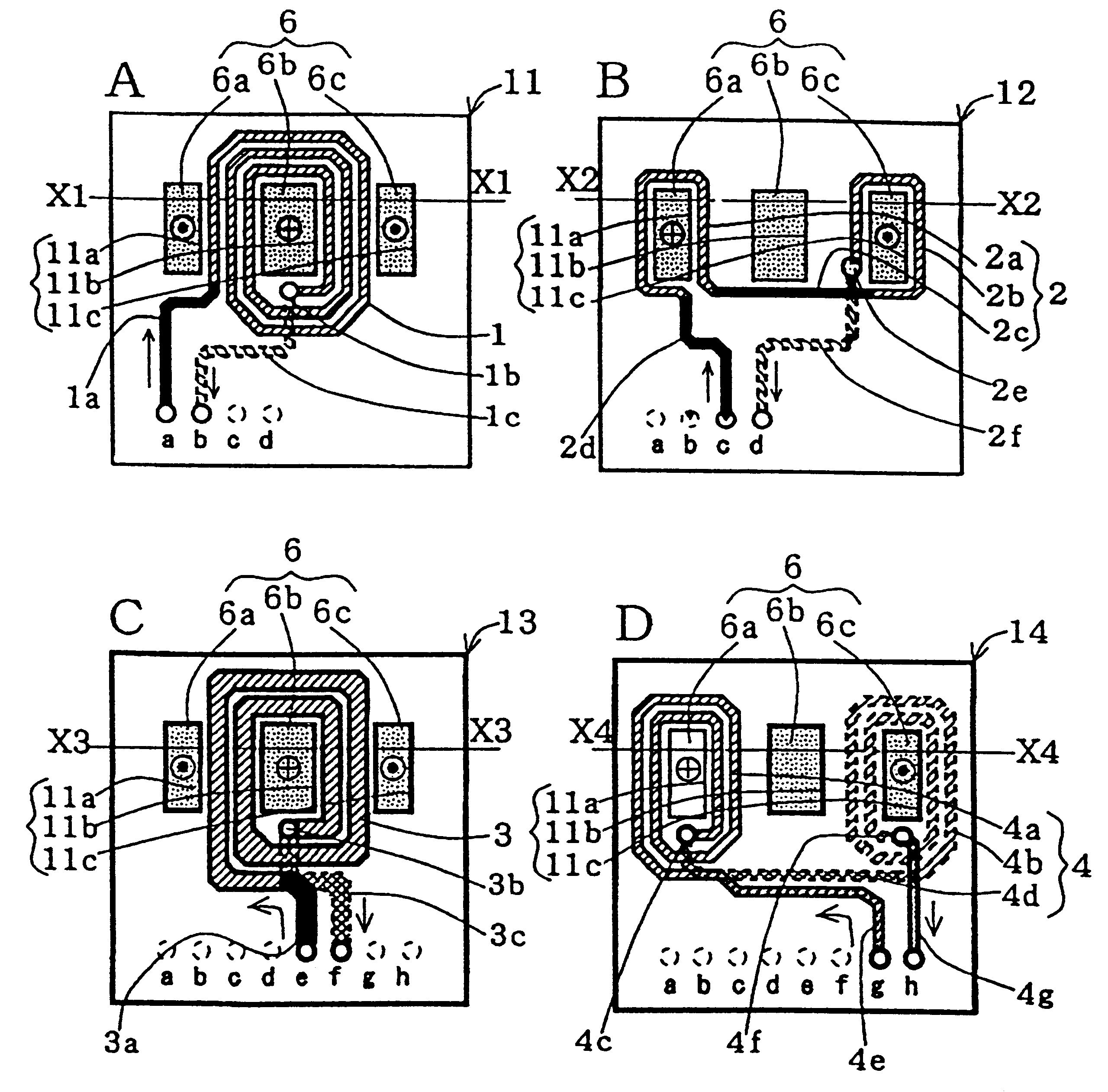
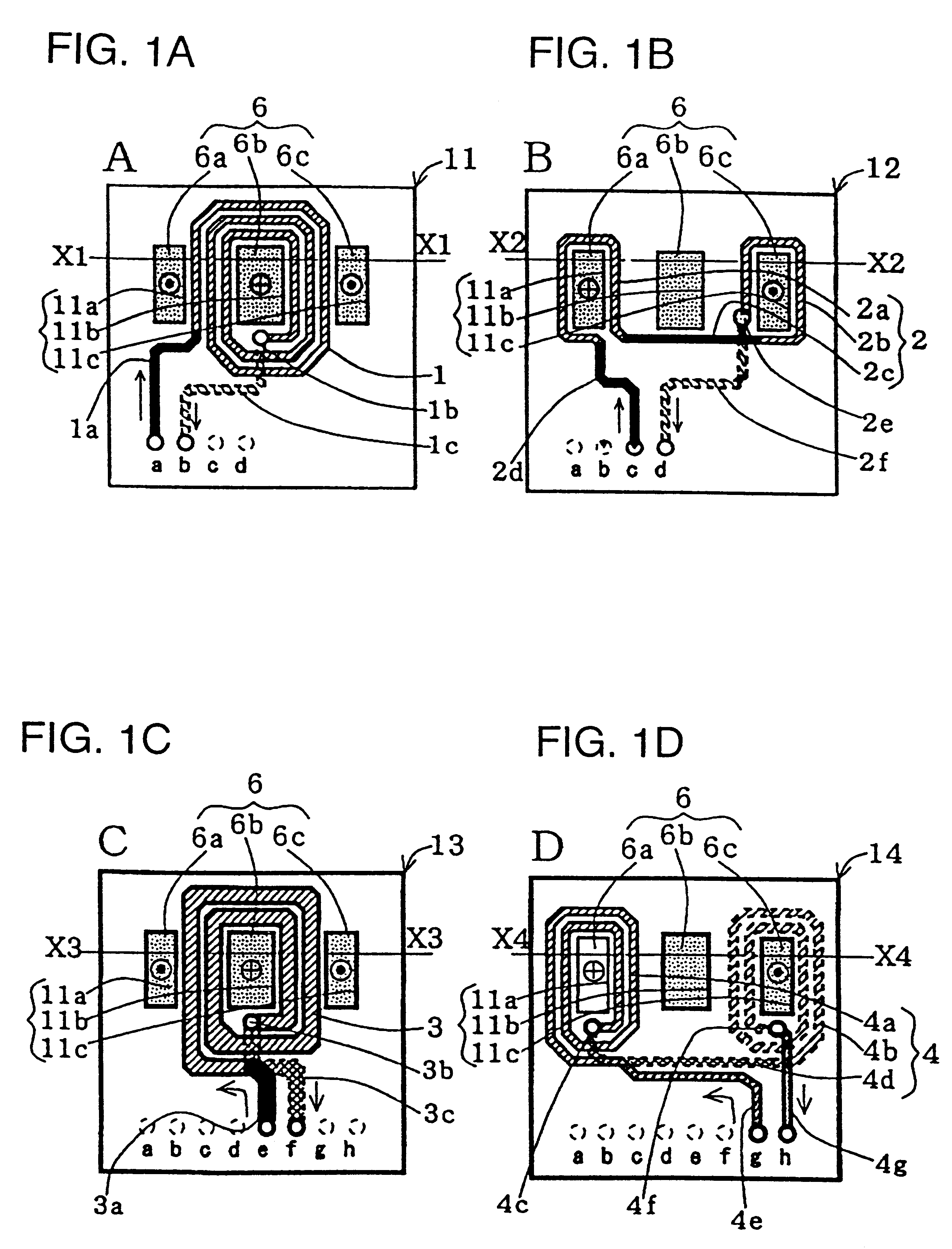
An embodiment of a coil device of the present invention is described below referring to FIG. 1A and FIG. 1B for a case where two inductor (coils) which can be regarded to be independently individual parts from each other are combined with one core.

In FIG. 1A, reference numeral 11 denotes a first printed coil substrate, and three rectangular through holes 11a-11c are formed in its center part in a line at appropriate intervals. A first printed coil 1 (a first intermediate printed coil) of three turns is formed in a winding manner clockwise from the outer side to the inner side on a surface of a first printed coil substrate 11 around the center through hole 11b among these three through holes 11a-11c. An external terminal of the first printed coil 1 is connected to an external terminal a through a connection wiring 1a. An internal terminal of the first printed coil 1 ...


PUM

PropertyMeasurementUnit
voltageaaaaaaaaaa
magnetic fieldsaaaaaaaaaa
magnetic fluxaaaaaaaaaa

Abstract

A coil device having a core having an intermediate leg and at least a pair of external legs arranged at equal intervals from the intermediate leg; a first printed coil provided on a first substrate which has an intermediate hole and a pair of external holes respectively inserted in the intermediate leg and the pair of external legs of the core, the first printed coil being wound around the intermediate hole; and a second printed coil provided on a second substrate which has an intermediate hole and a pair of external holes respectively inserted in the intermediate leg and the pair of external legs of the core, the second printed coil including a pair of external printed coils which are connected in series and are respectively wound around the pair of the external holes with the same number of turns but in opposite directions.

Description

1. Field of the InventionThe present invention relates to a coil device such as a transformer and an inductor to be used for electronic equipment, switching power supply apparatus or the like, and the switching power supply apparatus using it.2. Description of the Related ArtSwitching power supply apparatus have been widely used for a power supply units of various electronic devices such as personal computers, facsimile machines or the like. Especially, switching power supply apparatus including an isolated forward converter type as a DC-DC converter are suitably employed in laptop computers or the like.Such a switching power supply apparatus including an isolated forward converter generally comprises a power transformer, a driving transformer and a choke coil. These coil elements use coils and core parts, which are bulky and require substantial spaces to be mounted on a circuit board. As a result, it is very difficult to miniaturize the circuit board and switching power supply appa...

Claims


Application Information

Patent Timeline
Patent Type & Authority Patents(United States)
IPC IPC(8): H01F27/28H01F19/00H01F19/04H02M3/24H02M3/335H05K1/14H05K1/16H01F17/00H01F30/00H02M3/28
CPCH01F19/04H01F27/2804H02M3/335H02M3/33592H02M3/33576H02M2001/0064H05K1/144H05K1/165Y02B70/10H02M1/0064
Inventor MATSUMOTO, TADAHIKONAGAI, JUN
Owner MURATA MFG CO LTD
Why Eureka
Try Eureka