
Corner connectors and methods

a technology of connectors and corners, applied in the direction of rod connections, sofas, beds, etc., can solve the problems of increased labor and production costs, and increased competitive pressure, so as to reduce the weight and cost of box springs, increase labor and production costs, and facilitate the effect of conventional manufacturing techniques

Inactive Publication Date: 2001-09-11
MCCALL & BROOKS
View PDF3 Cites 41 Cited by
  • Summary
  • Abstract
  • Description
  • Claims
  • Application Information

AI Technical Summary

Benefits of technology

In addition to built-up mattress supports as aforedescribed, metal box spring manufacturers are utilizing relatively thin wooden bases to reduce weight and costs of box springs. Such bases again are formed from built-up wooden components which are first assembled in rectangular form with 90.degree. corners which are subsequently rounded with a band saw or the like. Rounding of the corners is time consuming and requires a skilled worker, increasing the cost of labor and production.
Thus with the aforesaid problems and disadvantages of previous manufacturing and construction methods, the present invention was conceived and one of its objectives is to provide a preformed corner connector and method for use in mattress support and box spring base assembly methods which is easy to incorporate into conventional manufacturing techniques.
It is still another objective of the present invention to provide a corner connector which allows a relatively unskilled laborer to accurately assemble a mattress support with little training or skill.
It is yet another objective of the present invention to provide a corner connector for a mattress support which is inexpensive to manufacture yet provides an aesthetically pleasing, uniform result.
It is yet another objective of the present invention to provide a box spring base which is relatively light in weight and inexpensive to manufacture.

Problems solved by technology

Manufacturers of furniture components such as mattress supports and box spring bases in recent years have fallen under great competitive pressure in recent years due to foreign imports, low local unemployment and increased local competition.
Pine and other lightweight woods are used with square corner posts in the initial construction of the mattress supports after which the corners are band-sawed, often with difficulty and sometimes with sufficient inaccuracy to require additional fabrication or repair.
Rounding of the corners is time consuming and requires a skilled worker, increasing the cost of labor and production.

Method used


Image

  • Corner connectors and methods
  • Corner connectors and methods
  • Corner connectors and methods

Examples


Embodiment Construction

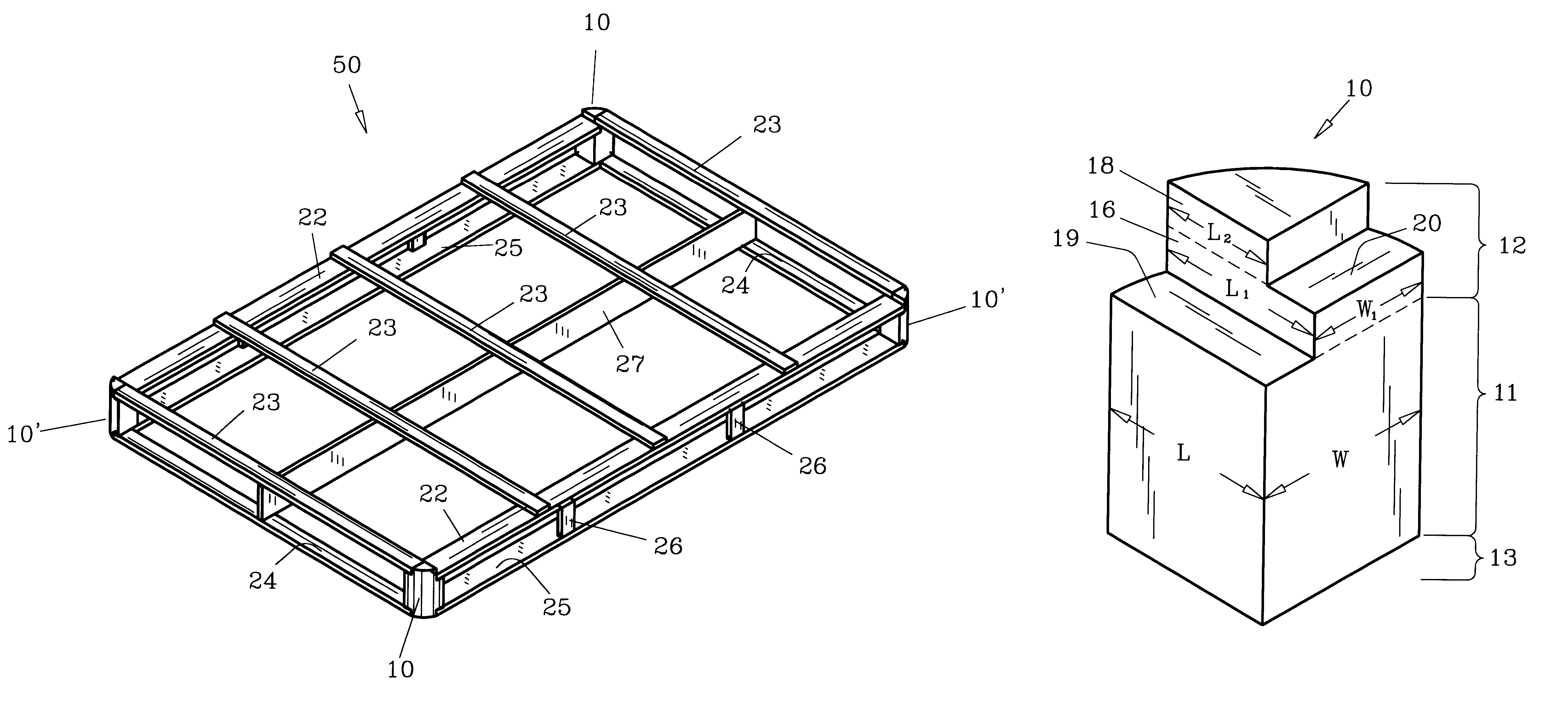
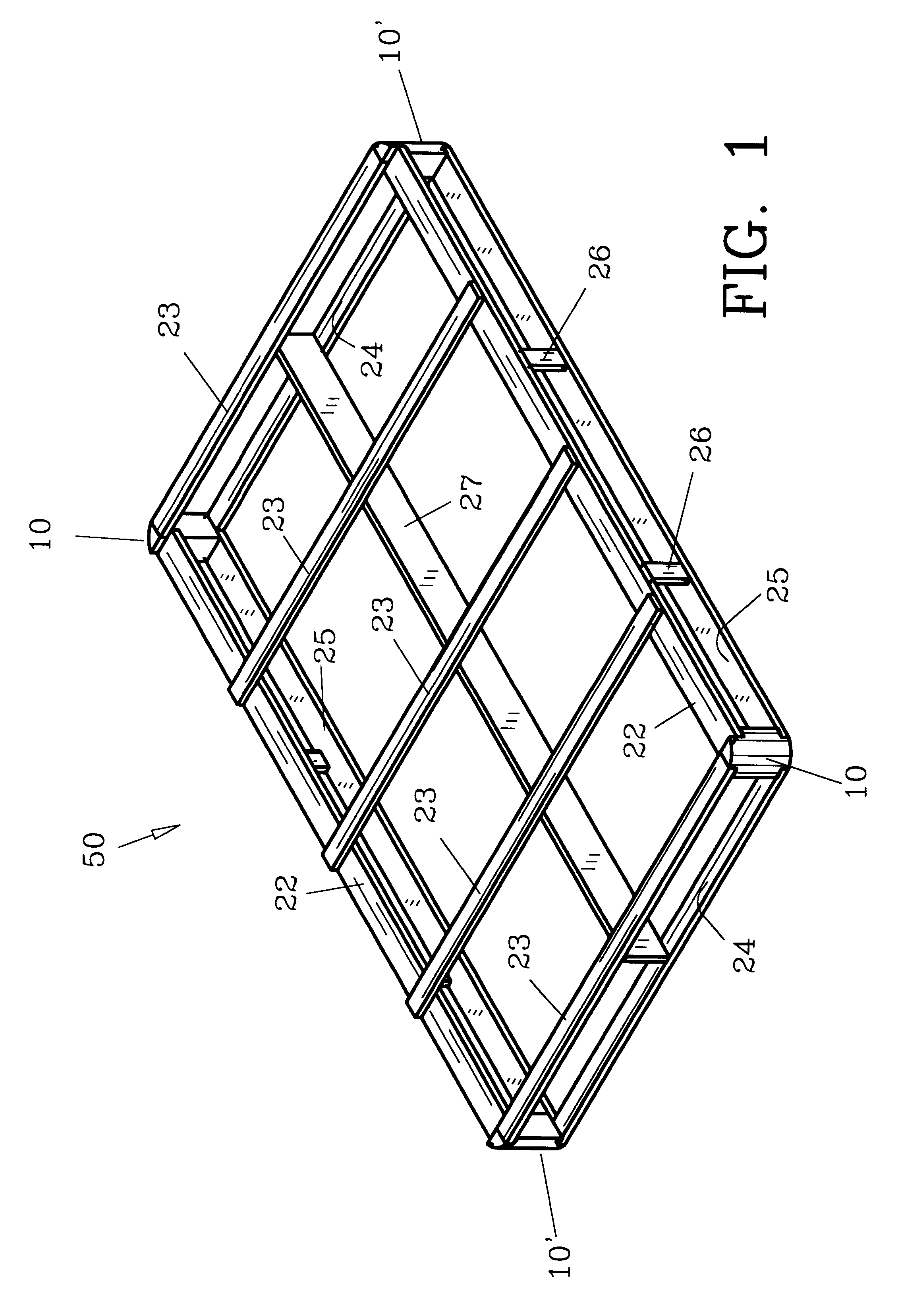
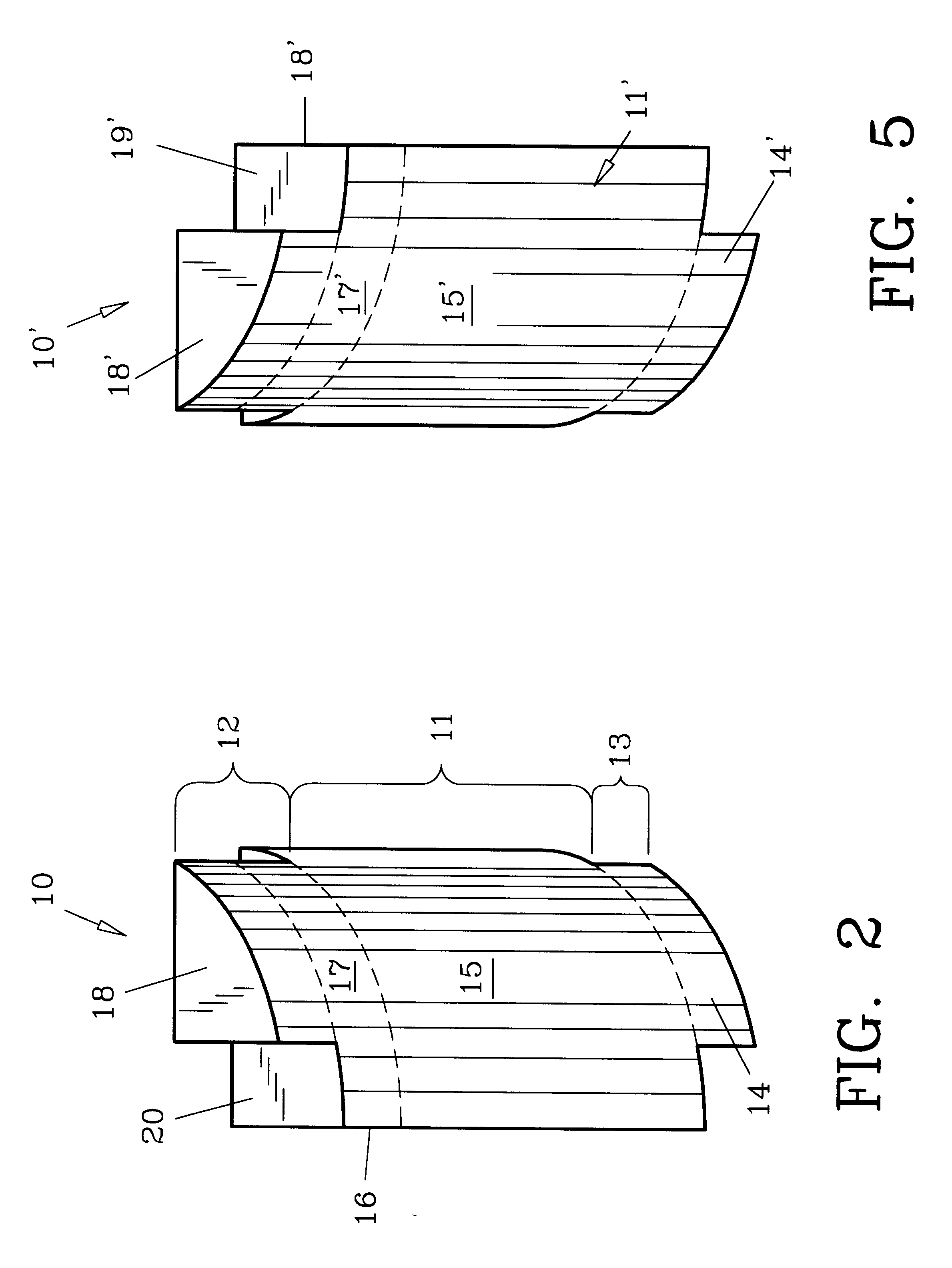
For a better understanding of the invention and its operation, turning now to the drawings, as shown in FIG. 1, preferred corner connectors 10, 10' can be used to form preferred mattress support 50 in place of conventional metal box springs to support mattresses for beds. Corner connectors 10, 10' are mirror images of each other as seen in FIGS. 2-7 showing different views thereof for clarity. Corner connector 10 is preferably unitarily formed from plastic by molding, though wood or other suitable materials can be used and sections made independently and connected, such as by adhesives, staples, screws or other fasteners. As shown in FIGS. 2 and 3, corner connector 10 includes a main central body or block section 11, a top section 12 and a lower section 13. Top section 12 includes a first planar member 16 (FIG. 3) which defines an arcuate rear surface or corner 17 (FIG. 2), which is coincidental with arcuate rear block surface or corner 15. Planar member 16 is positioned atop block ...


PUM


Abstract

Preformed corner connectors for mattress supports and box spring bases are provided to simplify and reduce the costs of constructing the same. The corner connectors are preferably unitarily formed by plastic molding or other suitable processes. The method of using the corner connectors includes preforming the same and attaching frame members with conventional fasteners for box spring bases and mattress supports as required.

Description

The invention herein pertains to mattress and box spring supports as are used in conventional beds. Particularly, the invention concerns the use of preformed corner connectors in mattress supports and box spring bases.DESCRIPTION OF THE PRIOR ART AND OBJECTIVES OF THE INVENTIONManufacturers of furniture components such as mattress supports and box spring bases in recent years have fallen under great competitive pressure in recent years due to foreign imports, low local unemployment and increased local competition. As a result, many manufacturers have eliminated conventional box springs that are normally used for mattress supports in beds and are instead supplying "built-up" mattress supports formed from wood. These built-up mattress supports are formed in rectangular fashion and are then sawed at each corner to fairly duplicate the rounded corners of conventional mattresses. Pine and other lightweight woods are used with square corner posts in the initial construction of the mattres...

Claims


Application Information

Patent Timeline
Patent Type & Authority Patents(United States)
IPC IPC(8): A47C19/00A47C19/02A47C23/00A47C23/06
CPCA47C19/02A47C23/06Y10T403/4602
Inventor MCCALL, JASON LANCE
Owner MCCALL & BROOKS
Learn More