
Optical disc device and optical disc discriminating method

a technology of optical discs and discs, applied in the direction of digital signal error detection/correction, instruments, recording signal processing, etc., can solve the problems of inability to use mechanical discrimination systems, device structure complexity, and increased manufacturing costs

Inactive Publication Date: 2001-09-11
SONY CORP
View PDF7 Cites 15 Cited by
  • Summary
  • Abstract
  • Description
  • Claims
  • Application Information

AI Technical Summary

Benefits of technology

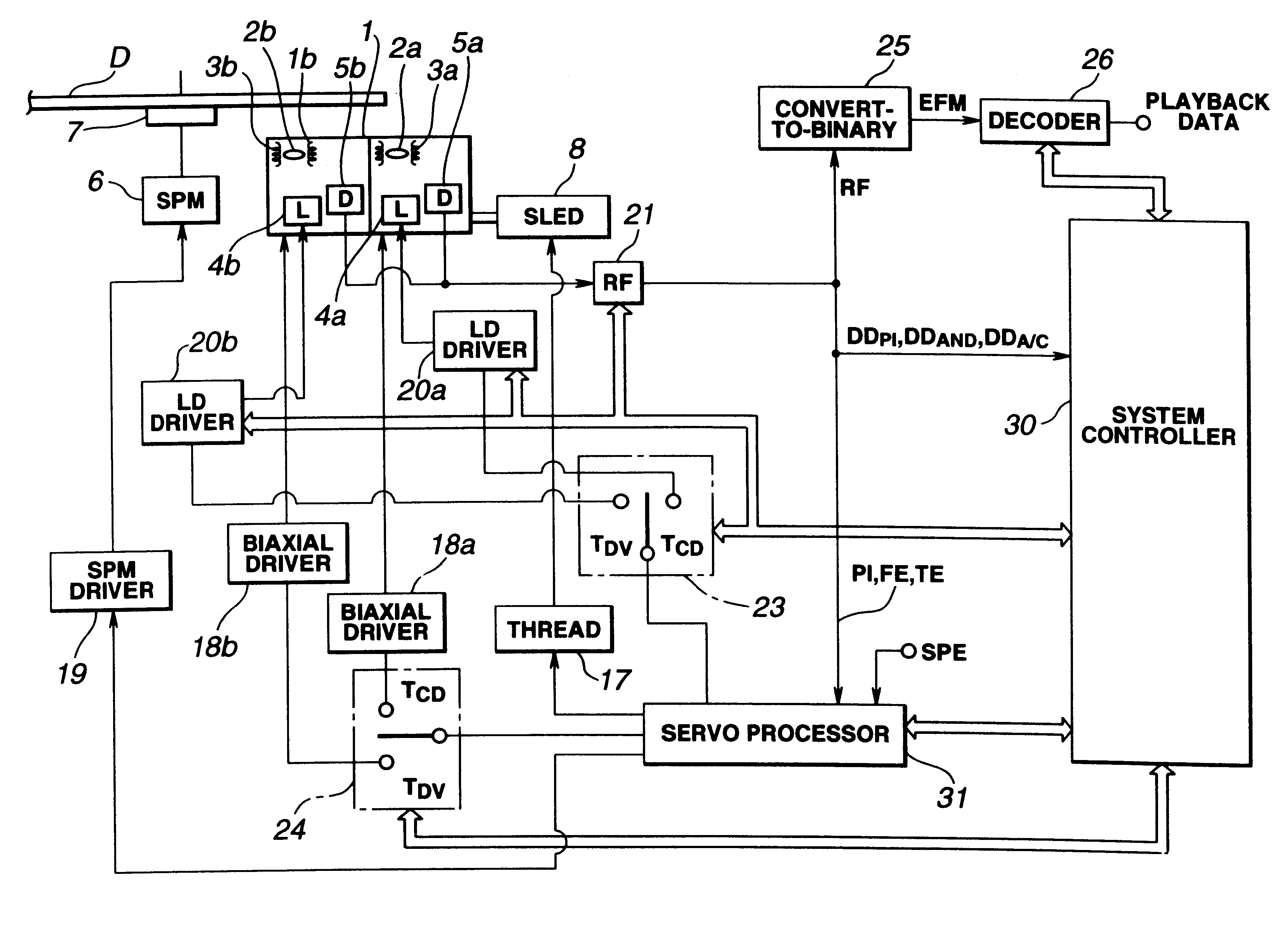
It is therefore an object of the present invention to provide an optical disc device and an optical disc discriminating method in which plural optical disc types having different numbers of signal recording layers are discriminated and an operating mode corresponding to the optical disc type is set by control means based on the discriminating output for reliable reproduction from the plural types of the optical discs.

Problems solved by technology

However, if the optical disc is not of the type housed in a cartridge, and moreover the optical disc itself is of the same size, this mechanical discrimination system cannot be used.
Moreover, if special components or units are provided for discriminating the disc type, such as a sensor, the device is undesirably complicated in structure, while the manufacturing costs are also raised.

Method used


Image

  • Optical disc device and optical disc discriminating method
  • Optical disc device and optical disc discriminating method
  • Optical disc device and optical disc discriminating method

Examples


Embodiment Construction

Referring to the drawings, preferred embodiments for carrying out the present invention will be explained in detail.

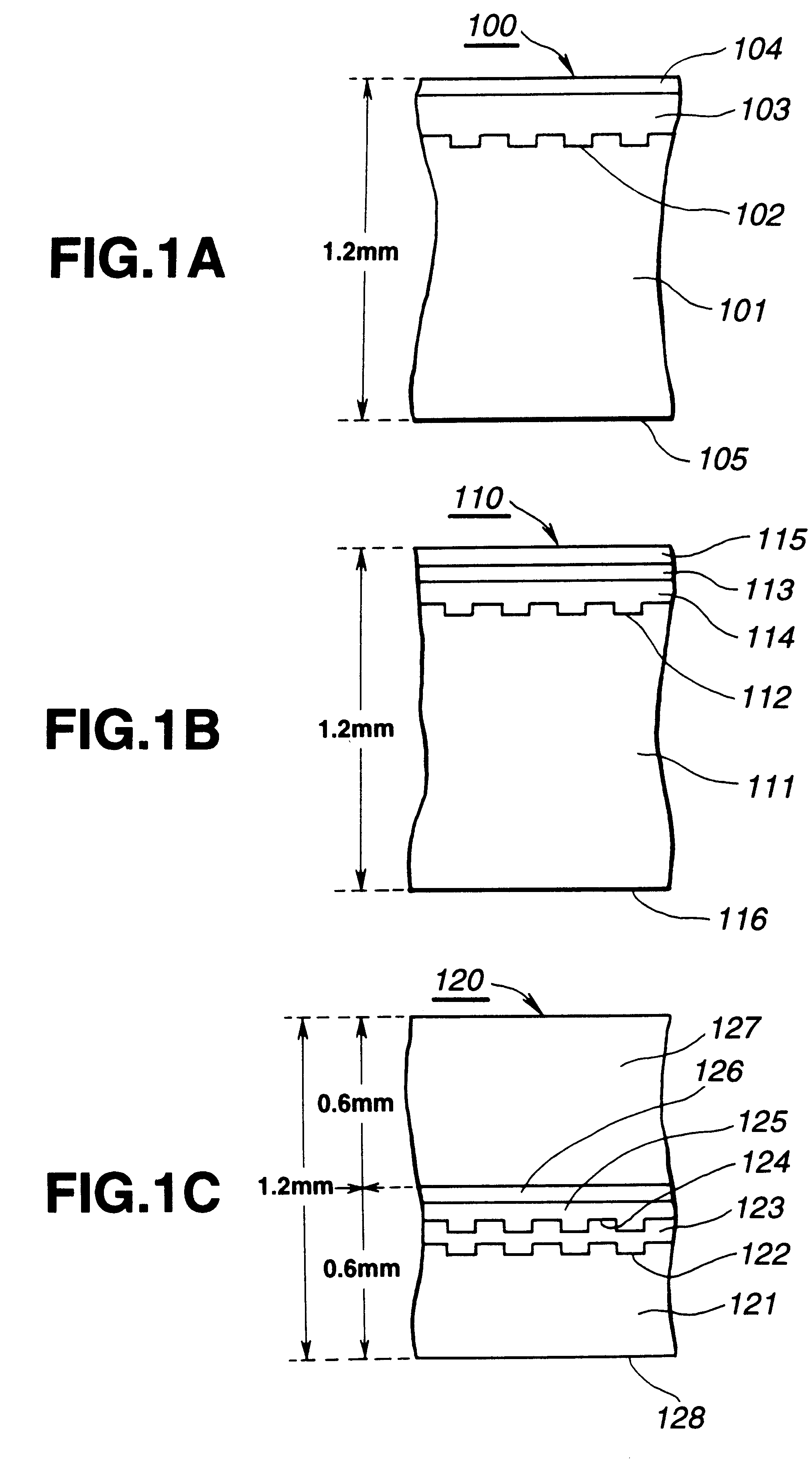
The present invention is applied to an optical disc device associated with a CD and a DVD. Before proceeding to the explanation of the optical disc device embodying the invention, the structures of the CD, CD-R and the DVD will be explained with reference to FIGS. 1a-1c. Meanwhile, the CD, CD-R and the DVD are all discs 12 cm in diameter.

FIGS. 1a, 1b and 1c illustrate a layered structure as cross-sections of the CD, CD-R and the DVD. As shown in these figures, the overall disc thickness of each of the CD, CD-R and the DVD is approximately 1.2 mm.

On the CD 100 shown in FIG. 1a, a disc substrate (transparent layer) 101 is molded from a transparent synthetic resin material, such as a transparent polycarbonate resin, polyvinyl chloride or acrylic resin, having high light transmission, mechanical resistance and resistance against chemicals. On a signal surface 102 of the di...


PUM

PropertyMeasurementUnit
diameteraaaaaaaaaa
thicknessaaaaaaaaaa
wavelengthaaaaaaaaaa

Abstract

An optical disc device includes a laser light source for radiating a laser light beam illuminated via an objective lens on a signal surface of an optical disc, a return light detection unit for detecting the reflected light radiated from the laser light source and reflected from the signal surface of the optical disc, a disc discriminating unit for discriminating the type of the optical disc based on a detection output of the return light detection unit, a unit for detecting tracking error signals of plural different types of different detection systems based on the detection output of the return light detection unit, a tracking unit for displacing the objective lens along the radius of the optical disc responsive to the tracking error signals for tracking-controlling a laser spot of the laser light focussed on the signal surface of the optical disc and a controlling unit for switching the detection system based on a discriminating output by the disc discriminating unit for selecting one of the plural types of the tracking error signals responsive to the types of the optical discs.

Description

1. Field of the InventionThis invention relates to an optical disc device capable of coping with plural types of optical discs, and a method for discriminating between plural types of optical discs.2. Description of Related ArtAs optical discs are in widespread use, optical discs of the compact disc CD type are used in many fields, including the field of musical applications. The CDs for music are usually designed as replay-only media. However, an overwrite type disc termed compact disc recordable (CD-R) is also commercialized.On the other hand, an optical disc termed a digital versatile disc / digital video disc (DVD) has also been developed as an optical disc suitable for multimedia use. This DVD is proposed as being adaptable to a wide field of applications, such as for use with video data, audio data or computer data. The DVD, which is an optical disc of the same size as the CD (12 cm in diameter), has a significantly increased recording capacity.Meanwhile, in keeping pace with th...

Claims


Application Information

Patent Timeline
Patent Type & Authority Patents(United States)
IPC IPC(8): G11B19/12G11B7/09G11B7/00G11B7/004
CPCG11B19/12G11B7/0943G11B7/0901G11B2007/0006G11B7/1374G11B7/0906G11B20/10388G11B2220/2537
Inventor KUMAGAI, EIJI
Owner SONY CORP
Learn More