Necking detecting and controlling method for melted-electrode arc welding

A technology of arc welding and consumable electrodes, which is applied in the field of constriction detection and control of consumable electrode arc welding, to achieve the effect of increasing the generation of sputtering and unobstructed reproduction

Active Publication Date: 2012-03-21
DAIHEN CORP
View PDF10 Cites 10 Cited by
  • Summary
  • Abstract
  • Description
  • Claims
  • Application Information

AI Technical Summary

Problems solved by technology

[0021] In order to solve the above-mentioned problems, the invention of claim 1 is a necking detection control method for consumable electrode arc welding, characterized in that the welding wire is fed forward by the welding torch and the arc generation state and short circuit are repeated between the welding wire and the base metal. In the consumable electrode arc welding of the state, the change of the voltage value or the resistance value between the welding wire and the base metal reaches the necking detection reference value to detect the precursory phenomenon of arc re-generation from the short circuit state, that is, the necking of the droplet, from From the constriction detection time, the arc is regenerated while reducing the welding current energized to the short-circuit load. When the arc is regenerated, the welding current is increased, and the elapsed time from the constriction detection time reaches a predetermined value before the arc is regenerated. At a determined reference time, the arc is regenerated by moving the welding wire back away from the base metal, and the back movement is stopped if the arc is regenerated

Method used


Image

  • Necking detecting and controlling method for melted-electrode arc welding
  • Necking detecting and controlling method for melted-electrode arc welding
  • Necking detecting and controlling method for melted-electrode arc welding

Examples


Embodiment approach 1

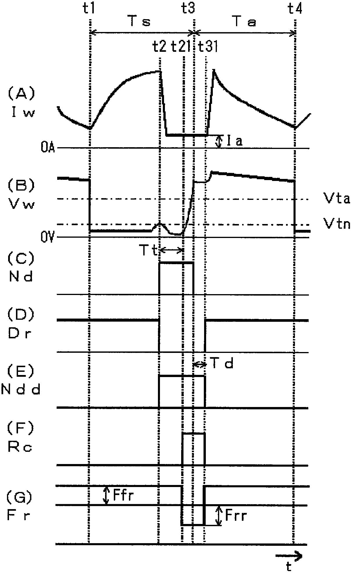
[0037] In the invention according to Embodiment 1, when the elapsed time t from the necking detection time reaches a predetermined reference time Tt before the arc is regenerated, the welding wire is moved backward to move away from the base material, thereby maintaining a state of a small current value. The arc is generated again, and if the arc is generated again, the aforementioned backward movement is stopped. In Embodiment 1, the above-mentioned retreating movement of the welding wire is performed by retreating feed. Therefore, the above-mentioned stop of the backward movement means stopping the backward feeding and returning to the normal forward feeding. Hereinafter, Embodiment 1 will be described.

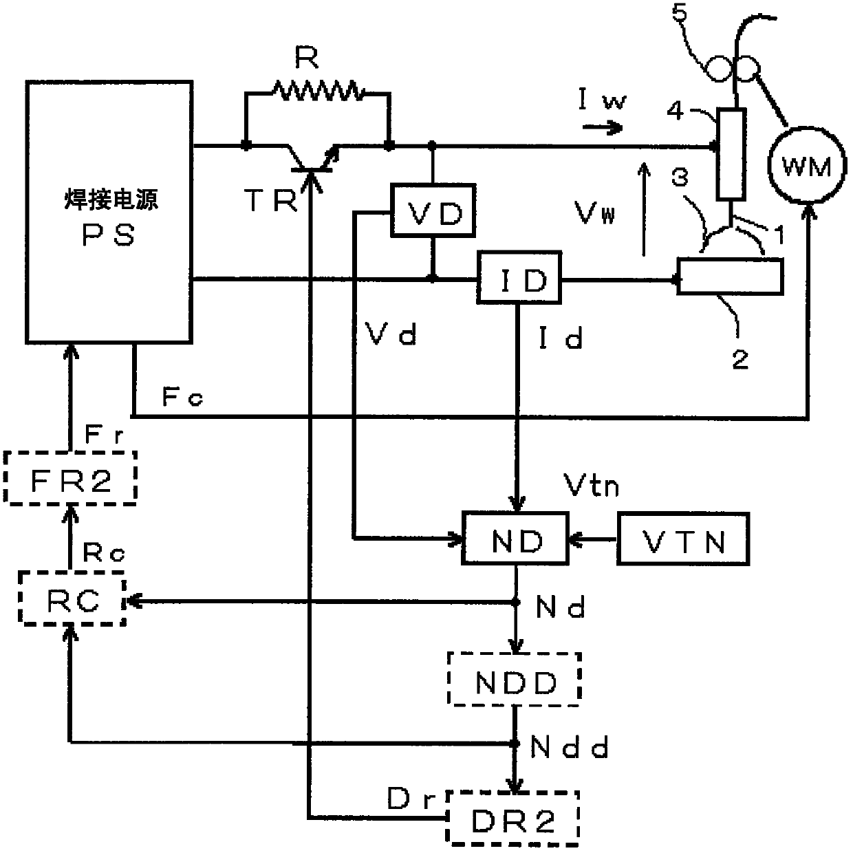
[0038] figure 1 It is a block diagram of a welding device for implementing the constriction detection and control method of consumable electrode arc welding according to Embodiment 1 of the present invention. exist figure 1 in, on and above Figure 6 The same symbols a...

Embodiment approach 2

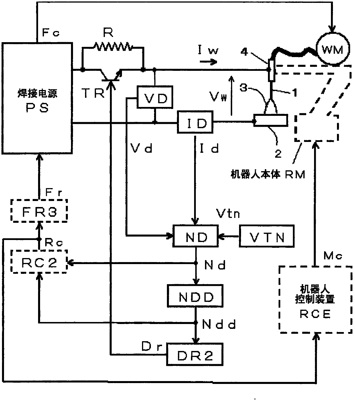
[0050] In the invention according to the second embodiment, as in the first embodiment, when the elapsed time t from the necking detection time reaches the predetermined reference time Tt before the arc is regenerated, the welding wire is moved backward to move away from the base metal, and the welding wire is kept. The arc is generated again in the state of a small current value, and if the arc is generated again, the aforementioned backward movement is stopped. In Embodiment 2, the welding torch is moved backward by the above-mentioned backward movement of the welding wire, and the height Lt of the welding torch is increased. Then, after the backward movement stops, the torch is moved forward to return the torch height Lt to the original height. During the backward movement, the forward feed of the wire continues. Hereinafter, Embodiment 2 will be described.

[0051] image 3 It is a block diagram of a welding device for implementing the constriction detection and control...


PUM


Abstract

The invention provides a necking detecting and controlling method for melted-electrode arc welding. During the melted-electrode arc welding, an electric arc can be smoothly regenerated even if molten drop necking is wrongly detected. Through the change in a voltage value (Vw) or a resistance value (Vw/Iw) of a welding wire and a base material, the premonitory phenomena of electric arc regeneration under the short-circuit state, i.e., molten drop necking, is detected according to a necking detection reference value. The welding current (Iw) which powers on a short-circuit load is reduced from the necking detection time (t2), so as to enable the regeneration (t3) of the electric arc. If the electric arc is regenerated, then the welding current is increased. When the self-necking detection period of time reaches the reference time (Tt) before the regeneration of the electric arc (t21), the necking detection is judged to be wrong. The welding wire is reversely moved at a set reverse feeding speed (Frr) so as to be far away from the base material, so that the electric arc is smoothly regenerated. If the electric art is regenerated, then the welding wire is moved at a set forward feeding speed (Ffr).

Description

technical field [0001] The invention relates to a necking detection control method for consumable electrode arc welding for detecting the necking phenomenon of molten droplets during a short circuit to reduce the welding current to improve welding quality. Background technique [0002] Figure 5 It is a diagram showing current-voltage waveforms and droplet transfer in consumable electrode arc welding in which short-circuit period Ts and arc period Ta are repeated. Figure 5 (A) shows the time change of the welding current Iw energized to the consumable electrode (hereinafter referred to as welding wire 1), Figure 5 (B) shows the time change of the welding voltage Vw applied between the welding wire 1 and the base metal 2, Figure 5 (C) to (E) show the state of the transfer of the droplet 1a. Below, refer to Figure 5 Be explained. [0003] During the short-circuit period Ts from time t1 to t3, the droplet 1a at the front end of the welding wire 1 is in a short-circuit state...

Claims


Application Information

Patent Timeline
Patent Type & Authority Applications(China)
IPC IPC(8): B23K9/10B23K9/00
Inventor 西坂太志
Owner DAIHEN CORP
Why Eureka
Try Eureka