Method and circuit for error correction, error correction encoding, data reproduction, or data recording

Inactive Publication Date: 2007-02-13
PANASONIC CORP
View PDF7 Cites 12 Cited by
  • Summary
  • Abstract
  • Description
  • Claims
  • Application Information

AI Technical Summary

Benefits of technology

[0017]A first object of the present invention is therefore to provide an error-correcting method and circ

Problems solved by technology

High density recording of digital information to the optical disk media makes read errors due to dust, disk scratches, and similar problems unavoidable during data reproduction.
Frequently accessing the DRAM bus is therefore a bottleneck to high speed reading and writing optical disks.
This means that when writing data from the modulator/demodulator to DRAM, or transferring data from DRAM to the modulator/demodulator, the data cannot be transferred continuously and must be sent in one-byte units, thereby degrading DRAM bus access performance.
Furthermore, because data can only be sent one byte at a time, bus access cannot be improved even if the DRAM bus width is in

Method used


Image

  • Method and circuit for error correction, error correction encoding, data reproduction, or data recording
  • Method and circuit for error correction, error correction encoding, data reproduction, or data recording
  • Method and circuit for error correction, error correction encoding, data reproduction, or data recording

Examples


embodiment 1

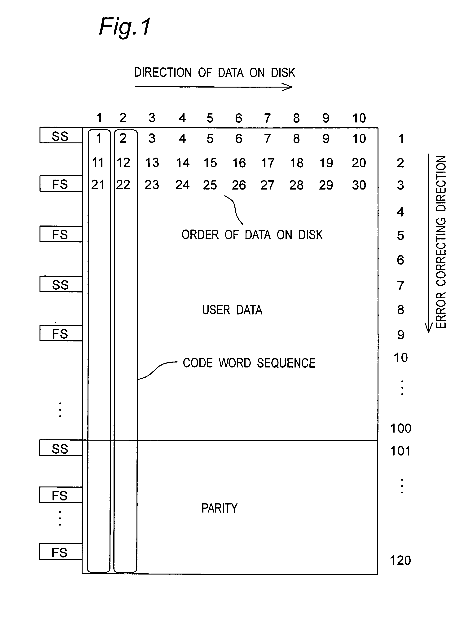
[0113]A first embodiment of the present invention is an error-correcting circuit for error-correcting reproduced data during data reproducing operation from an optical disk to which data is recorded based on a disk format shown in FIG. 1.

[0114]The recording format of data on an optical disk storing a reproduction signal that is error-corrected by an error-correcting circuit according to the present embodiment of the invention is described first below.

[0115]FIG. 1 schematically shows an ECC block frame configuration in the recording format of data recorded to the optical disk. An ECC block is an error-correcting data unit including a set of error-correcting code word sequences. One row contains 10 bytes of user data or parity, and a frame synchronization signal FS is inserted every two rows. The data strings bracketed by frame synchronization signal FS are called a frame. One frame therefore is equivalent to two rows in this embodiment of the invention. The error-correcting codes are...

embodiment 2

[0146]A second embodiment of the invention is an error-correcting coding circuit for achieving error-correcting coding of data when recording the data to an optical disk recorded with the disk format as shown in FIG. 1.

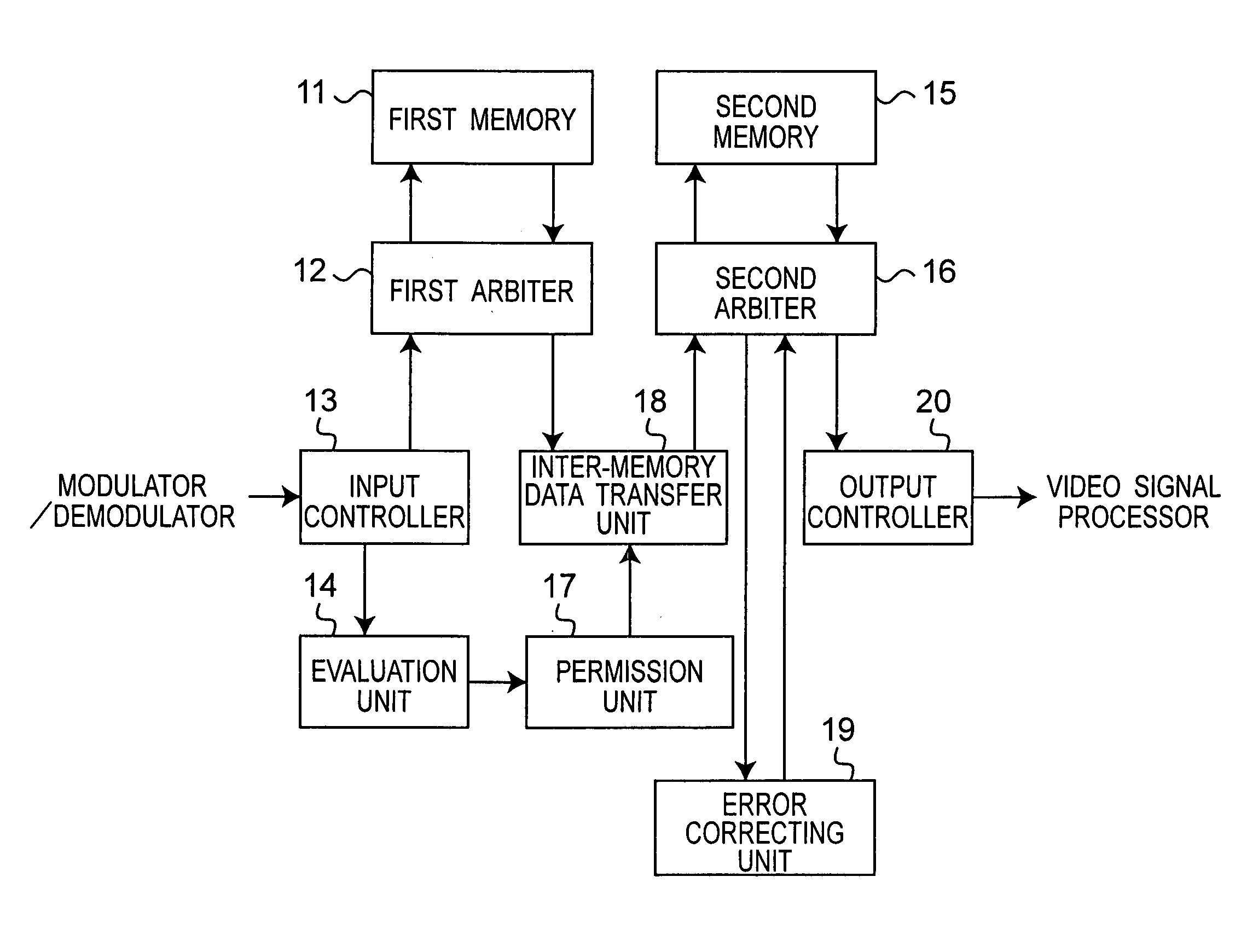
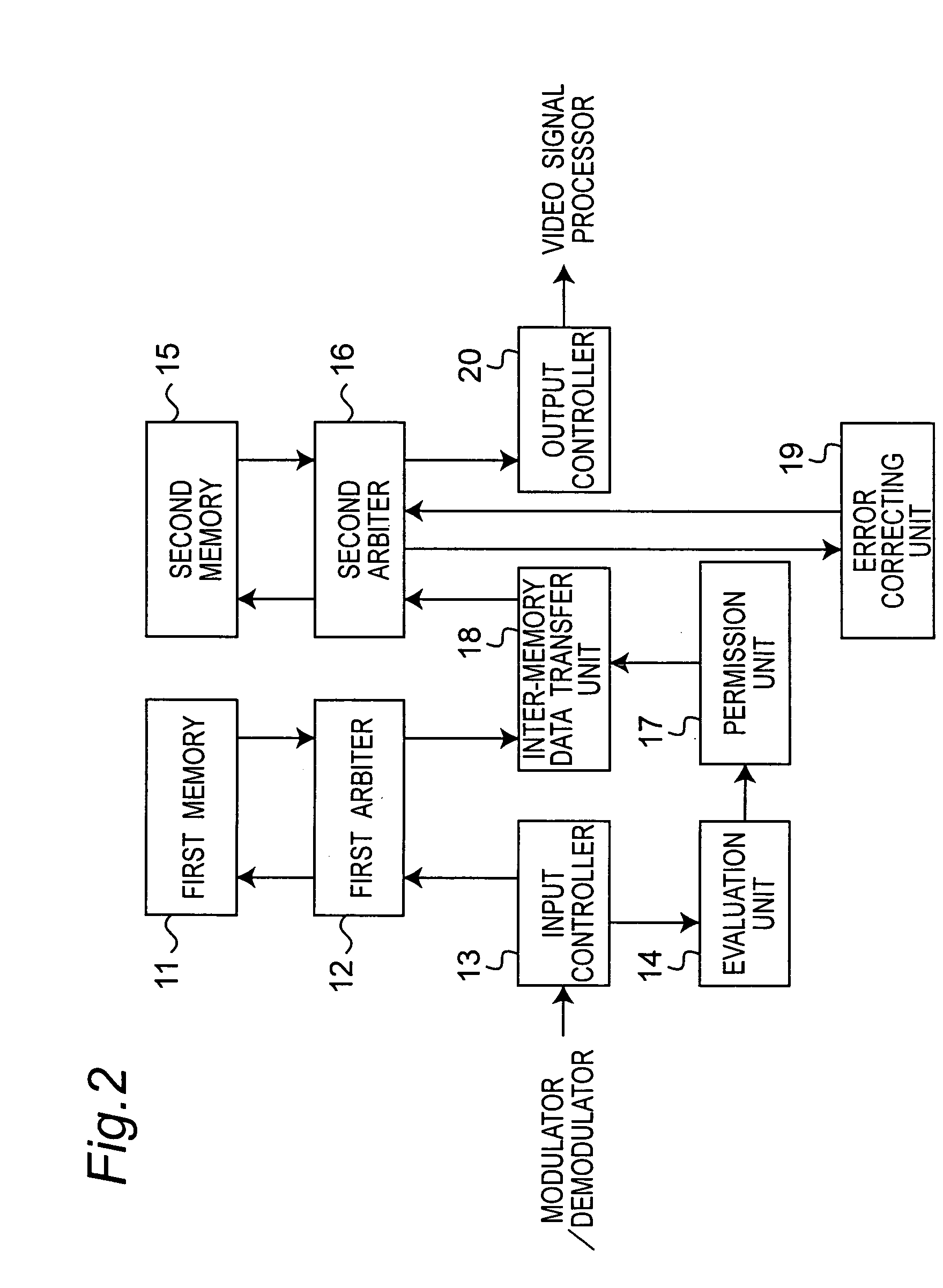
[0147]FIG. 9 is a block diagram of an error-correcting coding circuit according to this embodiment of the invention.

[0148]The error-correcting coding circuit includes elements 31 to 40. The error-correcting coding circuit applies error-correcting coding process to data received from the video signal processor to output the result to the modulator / demodulator.

[0149]The first memory 31 is a memory with a 4 byte wide bus, such as DRAM. The first arbiter 32 is a bus arbiter as known from the literature for arbitrating I / O to the first memory 31. The input controller 33 stores the user data to the first memory 31 and has a multiplier for calculating the address in the first memory 31. The error-correcting coding unit 39 applies error-correcting coding process to the user d...

embodiment 3

[0167]An optical disk apparatus for recording and reproducing video information using an optical disk is described next as a third embodiment of the invention.

[0168]FIG. 12 is a block diagram of an exemplary optical disk apparatus according to this embodiment of the invention. The optical disk apparatus has an optical head 1301, a recording / reproducing circuit 1302, a modulator / demodulator 1303, an ECC processor 1304, and a video signal processor 1307 for compressing video signals or decompressing and restoring compressed video signals. The ECC processor 1304 includes an error-correcting circuit 1305 described in the first embodiment and an error-correcting coding circuit 1306 according to the second embodiment.

[0169]During reproduction operation, the optical disk apparatus scans the optical disk with the optical head 1301 and the recording / reproducing circuit 1302 then digitizes the signal obtained by the scanning. The modulator / demodulator 1303 then demodulates the signal and erro...


PUM


Abstract

Data is read from a recording medium and the reproduced data is deinterleaved and stored to a first memory while input/output to/from the first memory is arbitrated. It is determined whether a predetermined number of data units is stored to the first memory. Based on the result data, it is determined whether transfer of the data stored in first memory to a second memory is permitted. If data transfer is permitted, the reproduced data is transferred from the first memory to the second memory, during which time input/output to/from the second memory is arbitrated. The reproduced data stored to the second memory is then error corrected, and user data contained in the error corrected reproduction data is externally output from the second memory.

Description

BACKGROUND OF THE INVENTION[0001]1. Technical Field[0002]The present invention relates to a process for reproducing data from a recording medium to which interleaved data is recorded, and to a process for recording data to such a medium. The invention also relates to an error-correcting process applied when reproducing data from the recording medium, and to an error-correcting coding process applied when recording data to the recording medium.[0003]2. Related Art[0004]Recently, some products for reproducing at high speed video data, documents, and other types of digital information recorded in optical disks such as DVD and CD media have become widely available. High density recording of digital information to the optical disk media makes read errors due to dust, disk scratches, and similar problems unavoidable during data reproduction. To compensate for this problem, error-correcting coding is applied to the recording medium such as the optical disk on recording, and error-correctin...

Claims


Application Information

Patent Timeline
IPC IPC(8): G11B20/18G06F11/10G11B20/10G11C7/10
CPCG06F11/1008G11B20/10527G11C7/1006G11B20/18G11C2207/104
Inventor HASHIMOTO, YUICHITAKAGI, YUJIUSUI, MAKOTOKIMURA, NAOHIROYAMAMOTO, YOSHIKAZU
Owner PANASONIC CORP
Why Eureka
Try Eureka