Electrical connector for connecting a flexible printed circuit to a rigid printed circuit board

Inactive Publication Date: 2001-09-25
MOLEX INC
View PDF3 Cites 53 Cited by
  • Summary
  • Abstract
  • Description
  • Claims
  • Application Information

AI Technical Summary

Benefits of technology

An object of the present invention is to provide an electrical connector for joining a flexible printed circuit to a circuit board, which minimizes the relative size of the electrical connector and circuit board combination, thereby maximizing the use of inner space of a small electronic device when the circuit board is placed inside the electronic device.
To accomplish the objects of the present invention, there is provided an electrical connector for joining a flexible printed circuit to a rigid printed circuit board comprising a connector housing adapted to be mounted within an opening in the printed circuit board and including a circuit connecting portion for receiving the flexible printed circuit; a plurality of connection terminals mounted within the housing and terminating in surface mount portions wherein upper surfaces of the surface mount portions are adapted to make contact with corresponding circuit traces on a lower surface of the printed circuit board; a ground terminal extending outwardly from each side of the connector housing wherein the upper surface of the ground terminals are coplanar with the upper surfaces of the surface mount portions of the connection terminals; and a circuit fastener rotatably mounted for up and down movement on the connector housing adapted to secure the flexible printed circuit within the circuit connecting portion of the housing whereby, when the electrical connector is placed and fixed within the opening of the circuit board, the combined profile of the connector and circuit board assembly is reduced by the thickness of the circuit board as compared to the prior art connector / circuit board structure.

Problems solved by technology

This brings about difficulty in the use of space in small electronic appliances.
Furthermore, since the ground terminal is located on a surface below the connector housing, it is difficult to solder to the ground circuit of the circuit board.

Method used


Image

  • Electrical connector for connecting a flexible printed circuit to a rigid printed circuit board
  • Electrical connector for connecting a flexible printed circuit to a rigid printed circuit board
  • Electrical connector for connecting a flexible printed circuit to a rigid printed circuit board

Examples


Embodiment Construction

Reference will now be made in detail to the preferred embodiments of the present invention, examples of which are illustrated in the accompanying drawings.

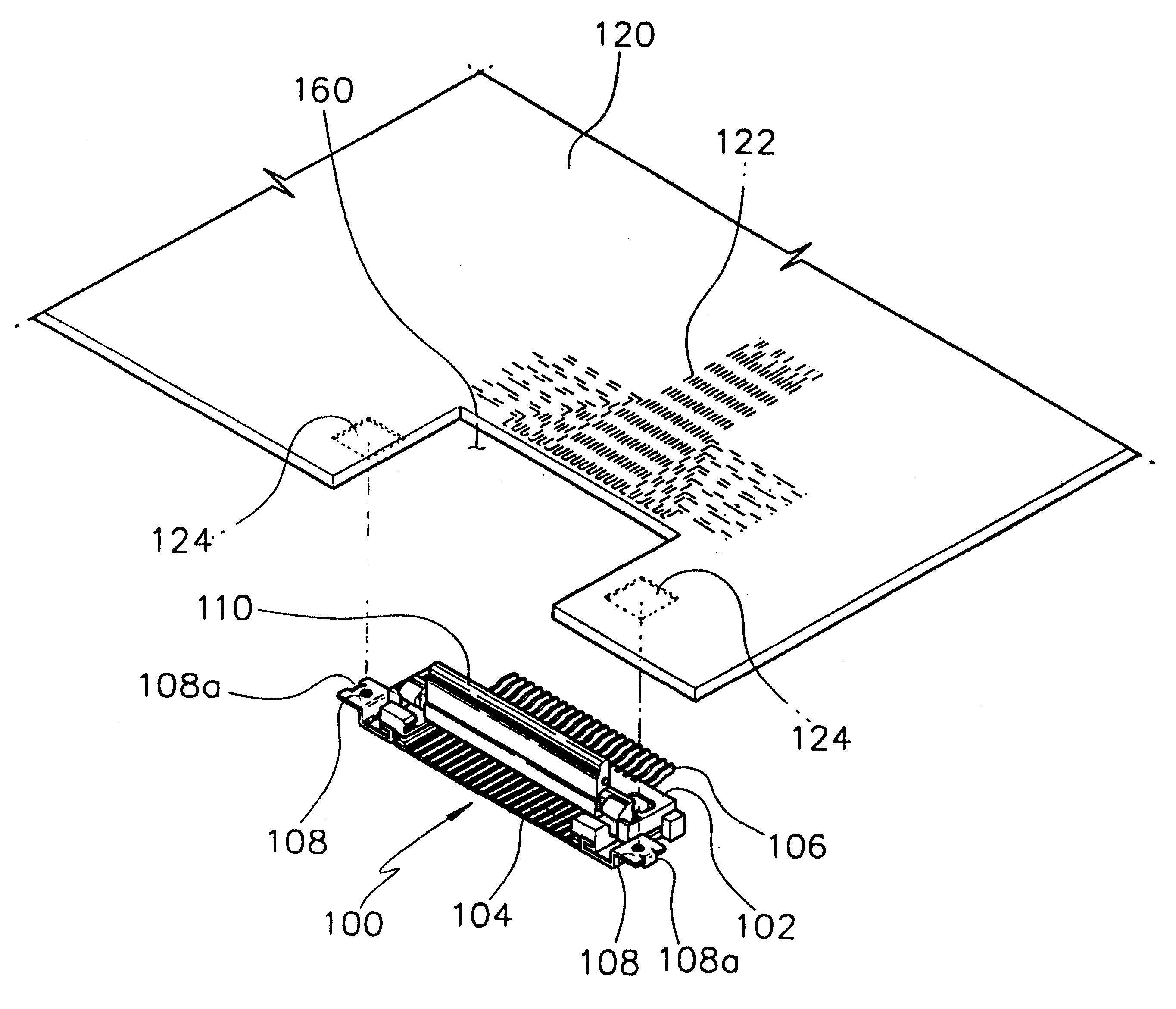
Referring to FIGS. 3 to 6, electrical connector 100 of the present invention includes a connector housing 102, a circuit connecting portion 104 formed in connector housing 102, a plurality of connection terminals 106 arranged in circuit connecting portion 104, a ground terminal 108 located at each side of connector housing 102, and a circuit fastener 110 rotatably mounted for up and down movement on connector housing 102.

Circuit connecting portion 104 is adapted to receive a flexible printed circuit 130 to mechanically and electrically join it to connection terminals 106. Circuit connecting portion 104 extends rearwardly from the front of connector housing 102, and is adapted to receive flexible printed circuit 130 therein. Connection terminals 106, electrically connected to connection traces 122 of circuit board 120, extend rearw...


PUM


Abstract

An electrical connector for joining a flexible printed circuit to a rigid printed circuit board comprises a connector housing adapted to be mounted within an opening in the printed circuit board and including a circuit connecting portion for receiving the flexible printed circuit, a plurality of connection terminals mounted within the housing and terminating in surface mount portions wherein upper surfaces of the surface mount portions are adapted to make contact with corresponding circuit traces on a lower surface of the printed circuit board, a ground terminal extending outwardly from each side of the connector housing wherein the upper surface of the ground terminals are coplanar with the upper surfaces of the surface mount portions of the connection terminals, and a circuit fastener rotatably mounted for up and down movement on the connector housing adapted to secure the flexible printed circuit within the circuit connecting portion of the housing, whereby when the electrical connector is placed in the opening of the circuit board the overall profile of the connected portion is reduced by the thickness of the circuit board.

Description

FIELD OF THE INVENTIONThe present invention relates to an electrical connector for connecting a flexible printed circuit to a rigid circuit board and, more particularly, to an electrical connector for joining a flexible printed circuit to a rigid circuit board when the connector is mounted within an opening of the circuit board.DISCUSSION OF RELATED ARTIn general, a connector is a connecting device for electrically joining wires, circuit boards and other circuit devices. The electrical connector in this specification is a device which is electrically joined to a printed circuit board of a small electronic apparatus, such as an LCD module of notebook computer or camcorder, and which receives a flexible printed circuitFIG. 1 is an exploded perspective view showing a combination of a conventional electrical connector and printed circuit board, and FIG. 2 is a cross-sectional view of the combination structure of FIG. 1. Referring to FIGS. 1 and 2, conventional electrical connector 10 in...

Claims


Application Information

Patent Timeline
IPC IPC(8): H01R13/648H05K1/14
CPCH01R12/79H01R12/57H01R13/648H01R12/52H01R12/72
Inventor KIM, YONG SOOSHIN, HEE SECK
Owner MOLEX INC
Why Eureka
Try Eureka