Transfer roller

Inactive Publication Date: 2001-09-25
OKI DATA CORP
View PDF18 Cites 7 Cited by
  • Summary
  • Abstract
  • Description
  • Claims
  • Application Information

AI Technical Summary

Problems solved by technology

As a result, the photoconductive drum is contaminated, causing lines to appear in the printed image.
This decreases the print quality.
However, such treatments not only are insufficien

Method used


Image

  • Transfer roller
  • Transfer roller
  • Transfer roller

Examples


first embodiment

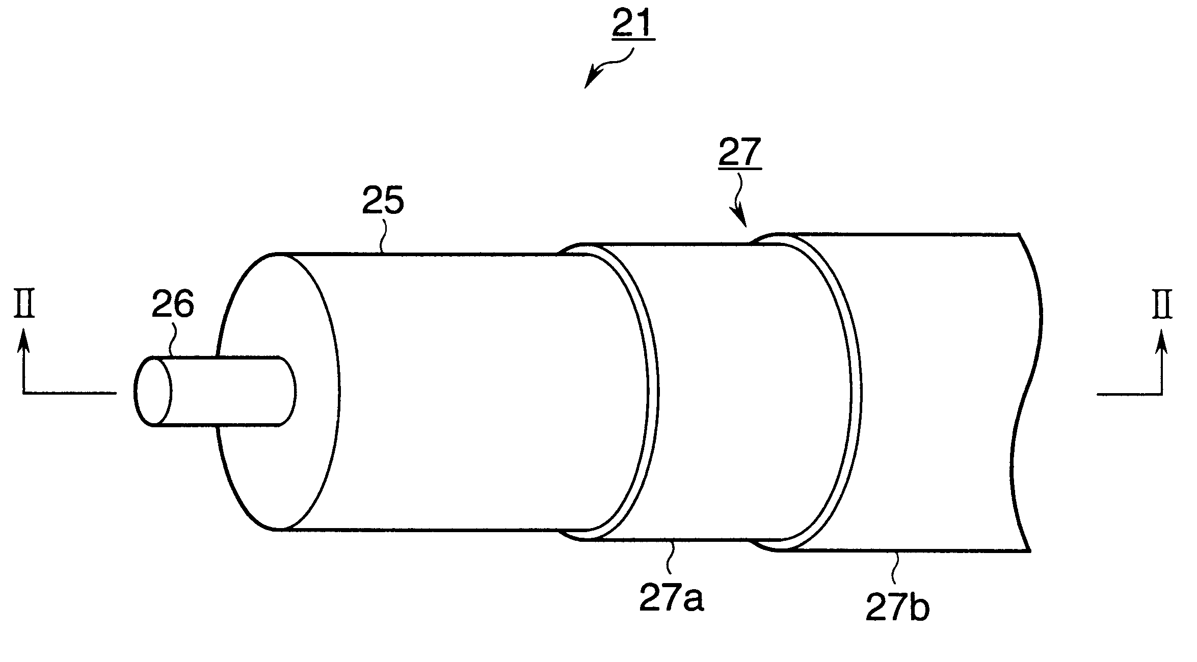
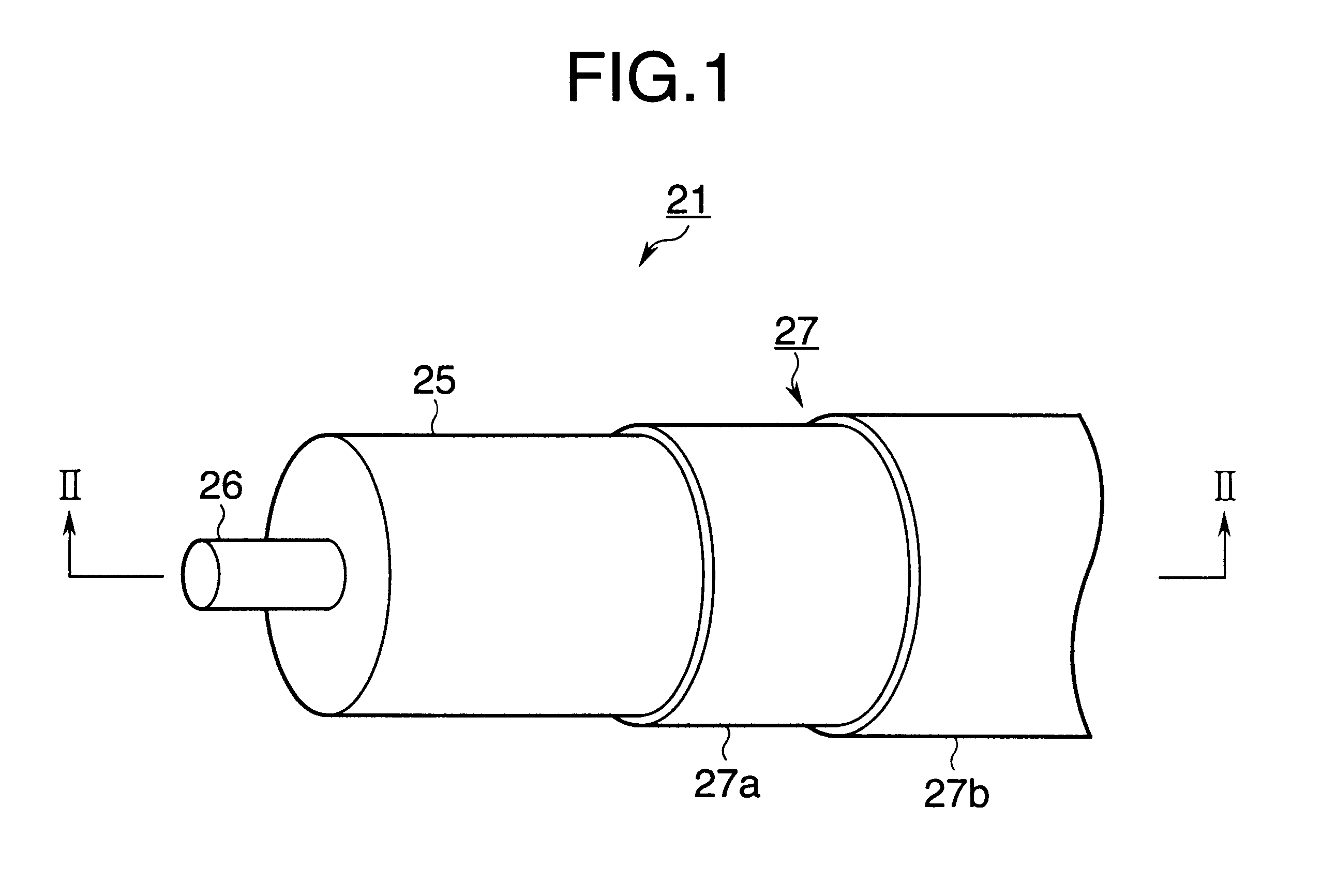
FIG. 1 is a fragmentary perspective view of a transfer roller according to a first embodiment.

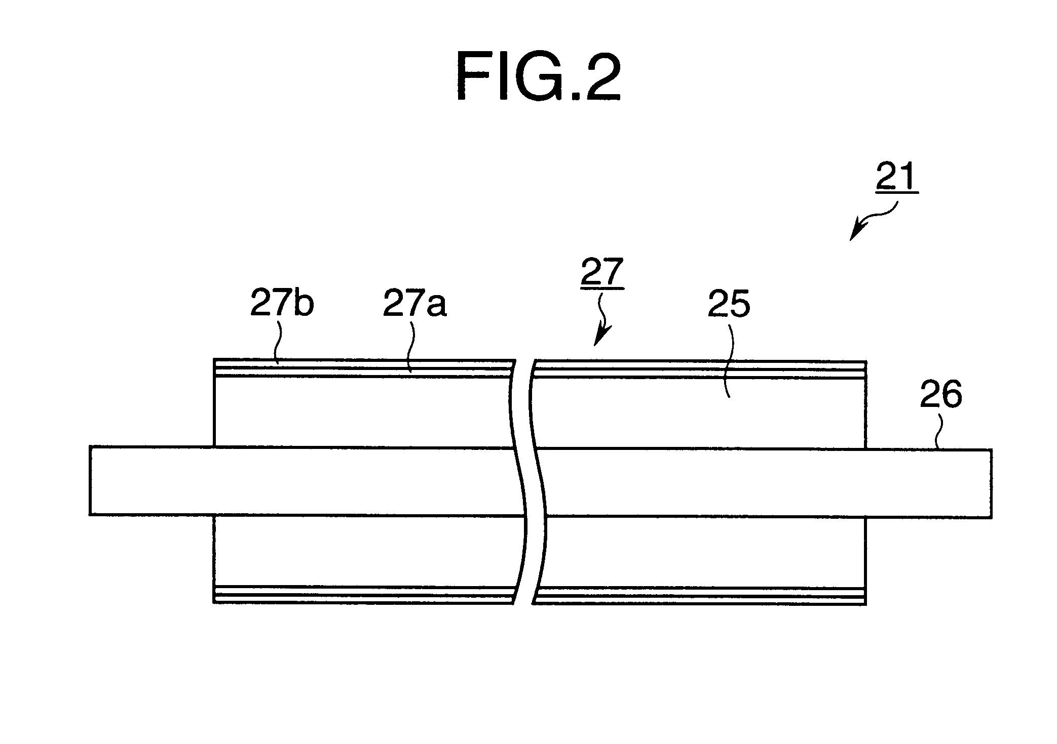
FIG. 2 is a longitudinal cross-sectional view taken along lines II--II of FIG. 1.

FIGS. 3 and 4 show characteristics of a resin tube 27 of FIG. 1.

FIG. 3 plots the voltage applied to a transfer roller 21 as abscissa and the resistance of the resin tube 27 as ordinate.

FIG. 4 plots the time for which the transfer voltage is applied to the transfer roller 21 as abscissa and the resistance of the resin tube 27 as ordinate.

In FIGS. 3 and 4, the solid lines indicate the characteristics of the transfer roller 21 when carbon black is added as an electrically conductive material and the dotted lines represent the characteristics of the transfer roller 21 when an organic ion electrically conductive material is added.

Referring to FIGS. 1 and 2, the transfer roller 21 includes a metal shaft 26, a sponge-like electrically semiconductive rubber roller 25 formed around the shaft 26, and an electrically semi...

second embodiment

Elements of the same construction as those of the first embodiment have been given the same reference numerals.

FIG. 5 is a longitudinal cross-sectional view of a transfer roller according to a second embodiment.

FIG. 6 is an enlarged fragmentary view of the transfer roller of FIG. 5.

Referring to FIGS. 5 and 6, a semiconductive resin tube 37 is formed on the rubber roller 25. The resin tube 37 is of a dual-layer structure having a lower layer 37a formed directly on the rubber roller 25 and an upper layer 37b formed on the lower layer 37a. The resin tube 37 is slightly longer than the rubber roller 25. When the resin tube 37 formed on the rubber roller 25 is subjected to heat shrinkage, the resin tube 37 extending beyond the longitudinal ends of the rubber roller 25 shrinks to wrap around the longitudinal end corners of the rubber roller 25, leaving a round portion m (FIG. 6) around the longitudinal end corners of the rubber roller 25.

When the transfer roller 31 receives a transfer vol...

example

The rubber roller 25 is in the form of an electrically semiconductive sponge and the resin tube 27 has a resistance of about 10.sup.8 .OMEGA.. The thickness of the resin tube 27 is about 100 .mu.m. The lower layer 27a has a thickness of about 20 .mu.m and the upper layer 27b has a thickness of about 80 .mu.m. The resistance of the lower layer 27a is about ten times as high as that of the upper layer 27b. The resin tube 27 has substantially the same total resistance as the rubber roller 25. Thus, the total resistance of the transfer roller 21 is substantially the same before and after the resin tuber 27 is formed over the rubber roller 25.

If only carbon black as an electrically conductive material is added to the resin tube 27, the electrical resistance increases with increasing the accumulated time of application of high voltage, causing changes in the overall resistance of the transfer roller. Therefore, it is necessary to make the resistance of the resin tube 27 as stable as possi...


PUM


Abstract

A transfer roller is used in an electrophotographic printer. The transfer roller rotates in contact with a rotating photoconductive drum with a print medium travelling therebetween. The transfer roller has a metal shaft around which a rubber roller is formed. The rubber roller is sponge-like and electrically semiconductive. The rubber roller is covered with a resin tube which has a lower layer formed on the rubber roller and an upper layer formed on the lower layer. One of the upper and lower layers has a higher sealing effect than the other of the upper and lower layers, and the other of the upper and lower layers has a higher stability of electrical resistance than the one of the upper and lower layer.

Description

1. Field of the InventionThe present invention relates to a transfer roller.2. Description of the Related ArtWith conventional electrophotographic printers, a charging device uniformly charges the surface of a photoconductive drum and then an LED head illuminates the charged surface to form an electrostatic latent image. The electrostatic latent is developed by a developing device into a toner image. Then, the toner image is transferred by a transfer device to a print medium. A fixing device subsequently fixes the toner image on the print medium.FIG. 7 is a perspective view of a transfer device of a conventional electrophotographic printer.A transfer roller 11 is in pressure contact with a photoconductive drum 12. The transfer roller 11 rotates in a direction shown by arrow A and the photoconductive drum 12 rotates in a direction shown by arrow B. The transfer roller 11 receives a transfer voltage or positive high voltage +E. The photoconductive drum 12 carries a toner image 13 form...

Claims


Application Information

Patent Timeline
IPC IPC(8): B41N7/00F16C13/00G03G15/16
CPCB41N7/00G03G15/1685F16C13/00B41N2207/04B41N2207/14B41N2207/02
Inventor KOYAMA, TATSUYAANDO, HIROKAZUFURUYA, SATORU
Owner OKI DATA CORP
Why Eureka
Try Eureka