Timepiece dial plate and timepiece dial plate manufacturing method

a manufacturing method and dial plate technology, applied in mechanical clocks, instruments, horology, etc., can solve the problems of increasing the manufacturing cost of timepiece dial plates, high manufacturing costs of indexes, and requiring several days of electroforming process to form a layer of several tens micrometer thicknesses, etc., and achieve the effect of luxurious appearan

Inactive Publication Date: 2001-09-25
SEIKO CORP
View PDF4 Cites 38 Cited by
  • Summary
  • Abstract
  • Description
  • Claims
  • Application Information

AI Technical Summary

Benefits of technology

According to the present invention, the timepiece dial plate comprises the upper plate and the lower plate, the indices having surfaces of complicated shapes are formed in the lower plate, the positioning legs are attached to the upper plate, and the functionally necessary rigidity

Problems solved by technology

Those indices, however, need high manufacturing costs because the indices must individually be subjected to many processes to form the facets.
However, the electroforming process needs several days to fo

Method used


Image

  • Timepiece dial plate and timepiece dial plate manufacturing method
  • Timepiece dial plate and timepiece dial plate manufacturing method
  • Timepiece dial plate and timepiece dial plate manufacturing method

Examples


Embodiment Construction

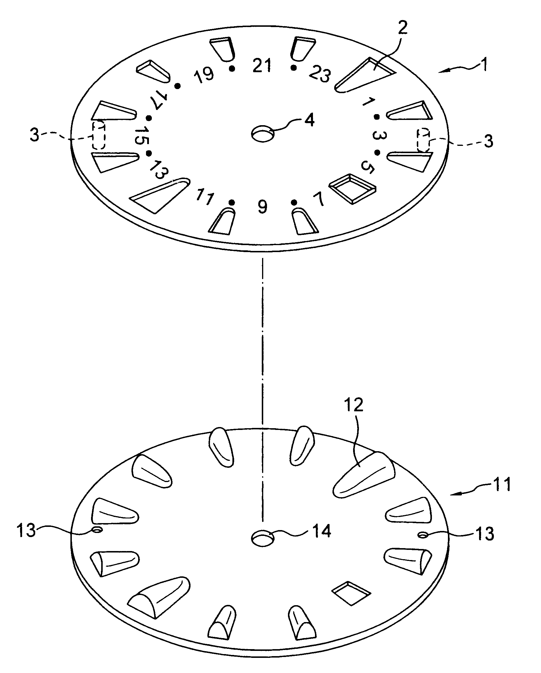
Referring to FIG. 1, a timepiece dial plate in a preferred embodiment according to the present invention comprises an upper plate 1 having the shape of a flat disk, and a lower plate 11 having the shape of a flat disk. The lower plate 11 is joined to the lower surface of the upper plate 1.

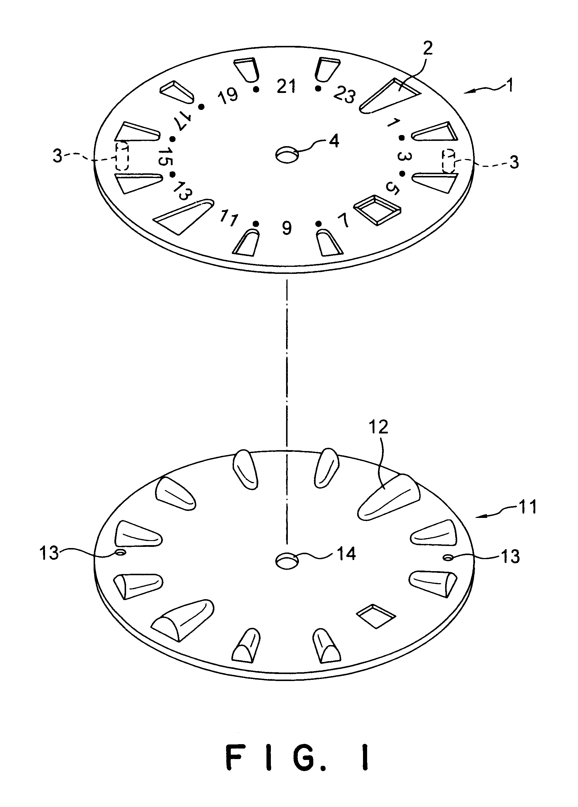
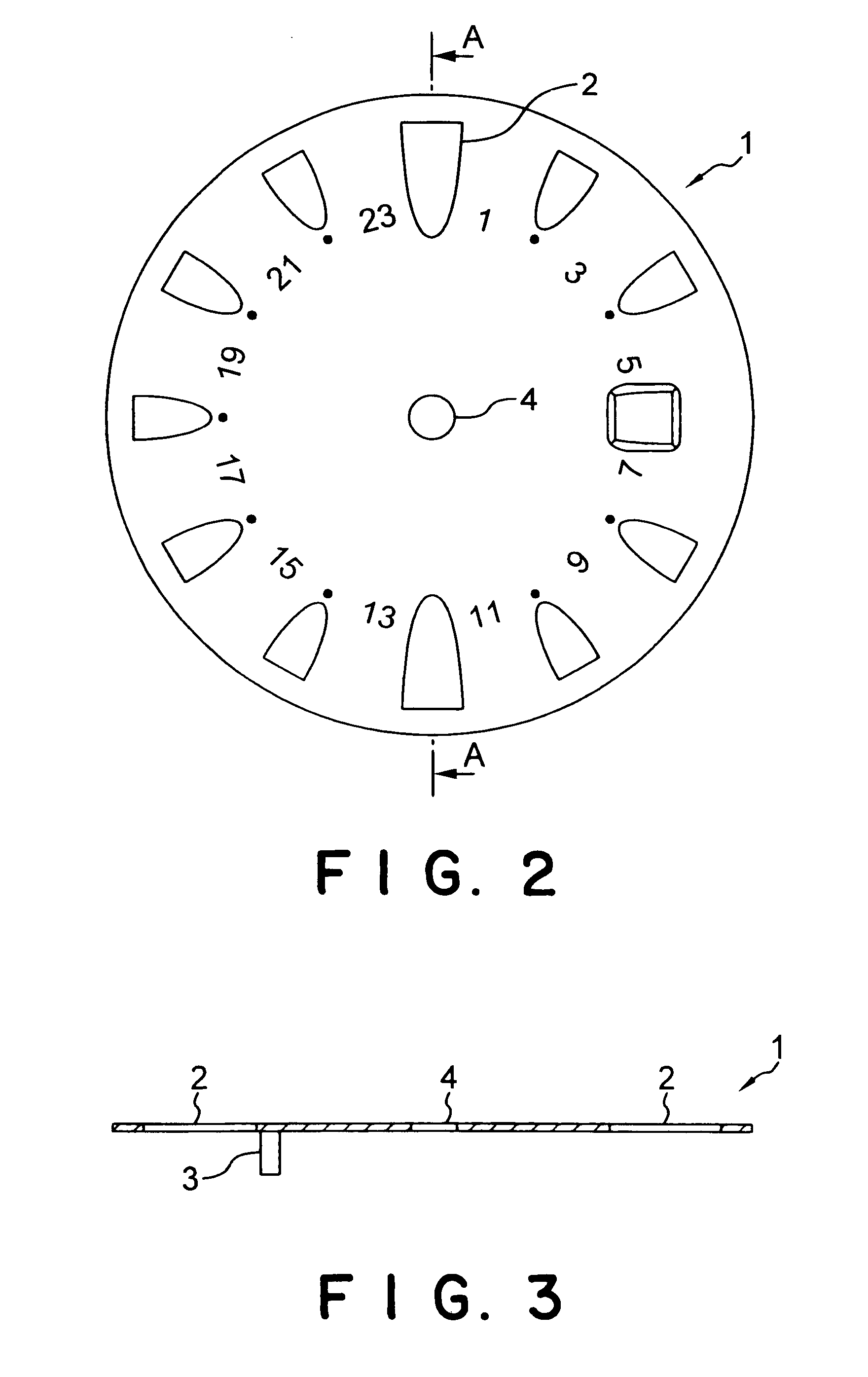
Referring to FIGS. 2 and 3, the upper plate 1 is provided with twelve holes 2 for receiving solid hour markers 12 therein so that the solid hour markers 12 protrude from the upper surface of the upper plate 1. A center hole 4 is formed in a central part of the upper plate 1. Two positioning legs 13 for positioning the timepiece dial plate relative to a movement are welded or brazed to the flat lower surface of the upper plate 1 so as to extend perpendicularly to the lower surface.

Referring to FIGS. 4 and 5, the twelve solid hour marks 12 are arranged on and protrude from the upper surface of the lower plate 11. The lower plate 11 is provided with two holes 13 through which the two positioning legs ...


PUM


Abstract

A timepiece dial plate comprises an upper plate (1) provided with holes (2, 4) and positioning legs (3) projecting from its lower surface so as to position the upper plate (1) relative to a movement; and a lower plate (11) provided on its upper surface with solid indices (12) to be fitted in the holes (2) of the upper plate (1) so as to protrude from an upper surface of the upper plate (1), and provided with holes (13) through which the positioning legs (3) of the upper plate (1) are extended. The upper plate (1) and the lower plate (11) are superposed so that the solid indices (12) of the lower plate (11) are fitted in the holes (2) of the upper plate (1), respectively, and protrude from the upper surface of the upper plate (1), and the positioning legs (3) of the upper plate (1) extend through the holes (13) of the lower plate (11), respectively.

Description

BACKGROUND OF THE INVENTION1. Field of the InventionThe present invention relates to a timepiece dial plate and, more particularly, to a timepiece dial plate provided on its face with relief indices resembling characters and such.2. Description of the Related ArtReferring to FIG. 10, a timepiece dial plate 100 is provided on its face with indices including hour markers 102 and a name marker 103. The time piece dial plate 100 is fixedly provided with two positioning legs 101 so as to project from the back surface of the timepiece dial plate 100. The two positioning legs 101 position and fix in place the timepiece dial plate 100 relative to a movement. Various finishing methods are applied to the manufacture of luxury timepieces to finish their indices including hour markers beautifully. For example, a timepiece dial plate 100 as shown in FIG. 11 is provided with indices including hour markers 102 set on the face thereof by a setting method. The setting method forms hour markers 102 h...

Claims


Application Information

Patent Timeline
IPC IPC(8): G04B19/10G04B19/06
CPCG04B19/10G04B19/065G04B19/06
Inventor SAKAI, SHIGEOISHIGURO, KATSUHIKOMATSUZAKI, MASAMI
Owner SEIKO CORP
Why Eureka
Try Eureka